Inter face for realizing automatic impedance matching and method thereof

A technology of impedance matching and automatic matching, applied in the direction of impedance network, line transmission parts, electrical components, etc., can solve the problems of increasing manufacturing cost, increasing complexity of production and maintenance, etc., and achieve the effect of reducing the risk of impedance mismatch

Inactive Publication Date: 2004-06-30
HUAWEI TECH CO LTD
View PDF0 Cites 13 Cited by
  • Summary
  • Abstract
  • Description
  • Claims
  • Application Information

AI Technical Summary

Problems solved by technology

In this way, multiple modules are derived from one port type, which not only increas...

Method used


Image

  • Inter face for realizing automatic impedance matching and method thereof
  • Inter face for realizing automatic impedance matching and method thereof
  • Inter face for realizing automatic impedance matching and method thereof

Examples


Embodiment Construction

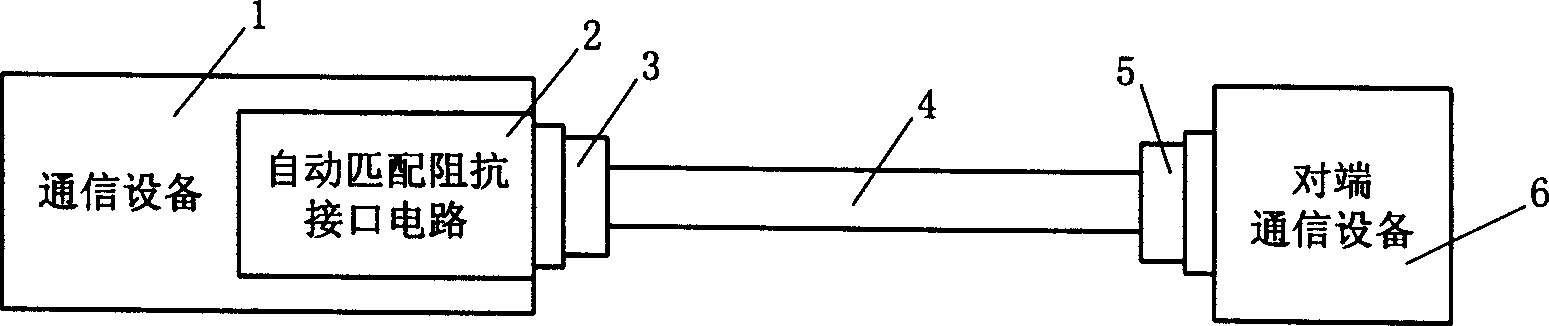
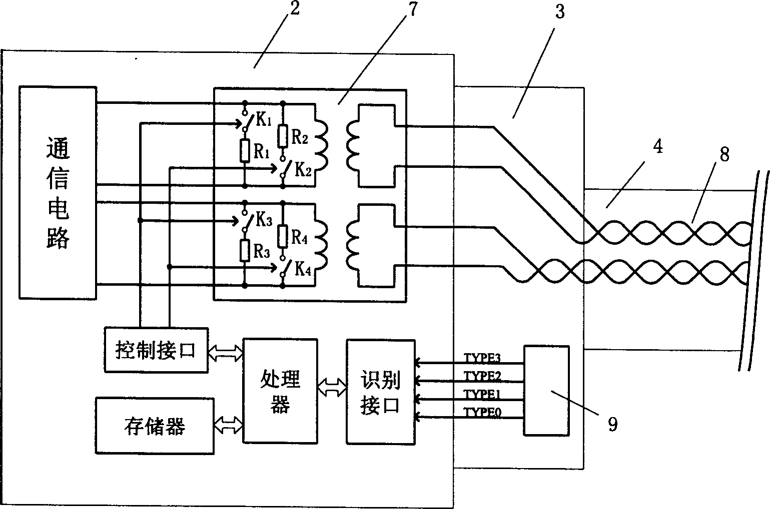
[0033] The interface for realizing impedance automatic matching proposed by the present invention has a structural block diagram such as figure 1 As shown, it includes: a transmission cable 4 used to connect the peer device 6 with the connector 3, the cable has the same impedance value as the peer device 6; it is used to connect the transmission cable 4 to the local device 1 connector 3, and an impedance matching interface circuit 2 for performing impedance matching on the local device according to the identification signal of the type of the transmission cable and the impedance value output by the connector.

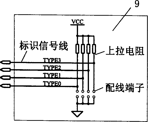
[0034] Connector cable impedance and type identification signal wiring circuit in the above interface, such as image 3 As shown, it includes: a pull-up resistor used to make the identification signal line in a normal signal state; a wiring terminal used to identify the transmission cable type and impedance value; used to output the transmission cable type and impedance...


PUM


Abstract

The interface comprises transmission cable and linker as well as impedance matching interface circuit. The cable and linker connects device at opposite device with the device in local device. Based on types of cable and id signal output from the linker, impedance matching is carried out for local device by the impedance matching interface circuit. First, the invention builds a mapping list between impedance of local device and matched impedance of cable and types. Impedance and type of cable is read out, and then matched value of impedance of local device is found out from the mapping list. Control of turning on/off resistance connected to the local device makes impedance of the local device match to impedance and type of cable. The invented interface and method can recognize impedance and type of cable with same impedance of opposite device so that different impedances are output in order to make impedances matched between opposite device and local device.

Description

technical field [0001] The invention relates to an interface and a method for realizing automatic impedance matching, belonging to the technical field of communication equipment. Background technique [0002] On routers or Ethernet switches, the E1 interface of the European standard and the T1 interface of the North American standard need to support cables with different impedances. The E1 interface usually needs to support 120Ω impedance cables and 75Ω impedance cables, while the T1 interface needs to support 100Ω impedance cables. . For equipment manufacturers, the unification of the two is more conducive to reducing the manufacturing cost and maintenance cost of the product. And for the E1 interface, since there are cables with two impedances of 120Ω and 75Ω, all communication devices on the market that support cable interfaces with different impedances usually need to manually configure the interface impedance according to the cable impedance used. The method of manual...

Claims


Application Information

Patent Timeline
IPC IPC(8): H03H7/38H04B3/03
Inventor 徐在水李晶林常华育
Owner HUAWEI TECH CO LTD
Why Eureka
Try Eureka