
Divider

A diverter, a part of the technology, applied in the direction of the hull bow, hull parts, hull, etc., can solve the problem of difficult to achieve high speed, and achieve the effect of increasing speed and increasing strength

Inactive Publication Date: 2004-07-07
冯永刚
View PDF0 Cites 0 Cited by
  • Summary
  • Abstract
  • Description
  • Claims
  • Application Information

AI Technical Summary

Problems solved by technology

and difficult to achieve high speed

Method used


Image

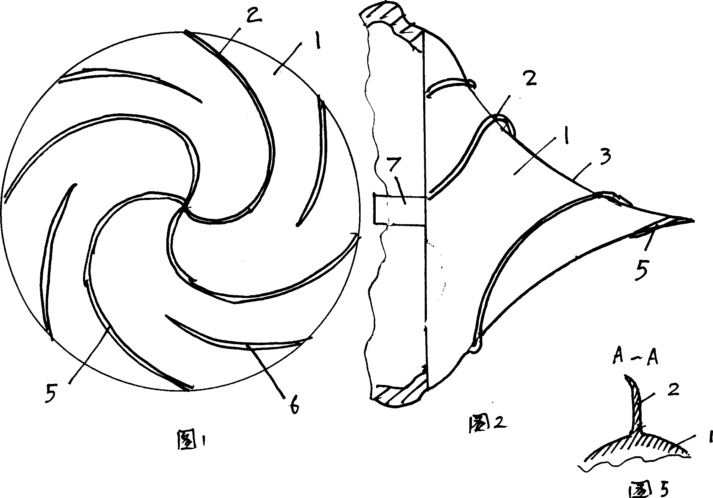
  • Divider
  • Divider
  • Divider

Examples


Embodiment Construction

[0017] A flow divider, in which spiral blades 2 are uniformly distributed on the surface of a cone 1 that is approximately conical. The spiral blades are spiral curves extending from the tip of the cone to the opposite direction of the cone surface.

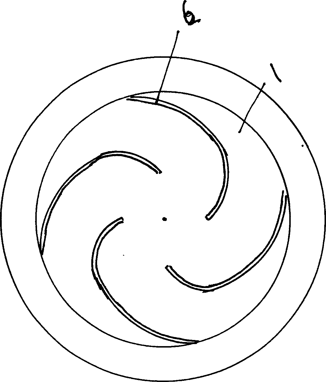
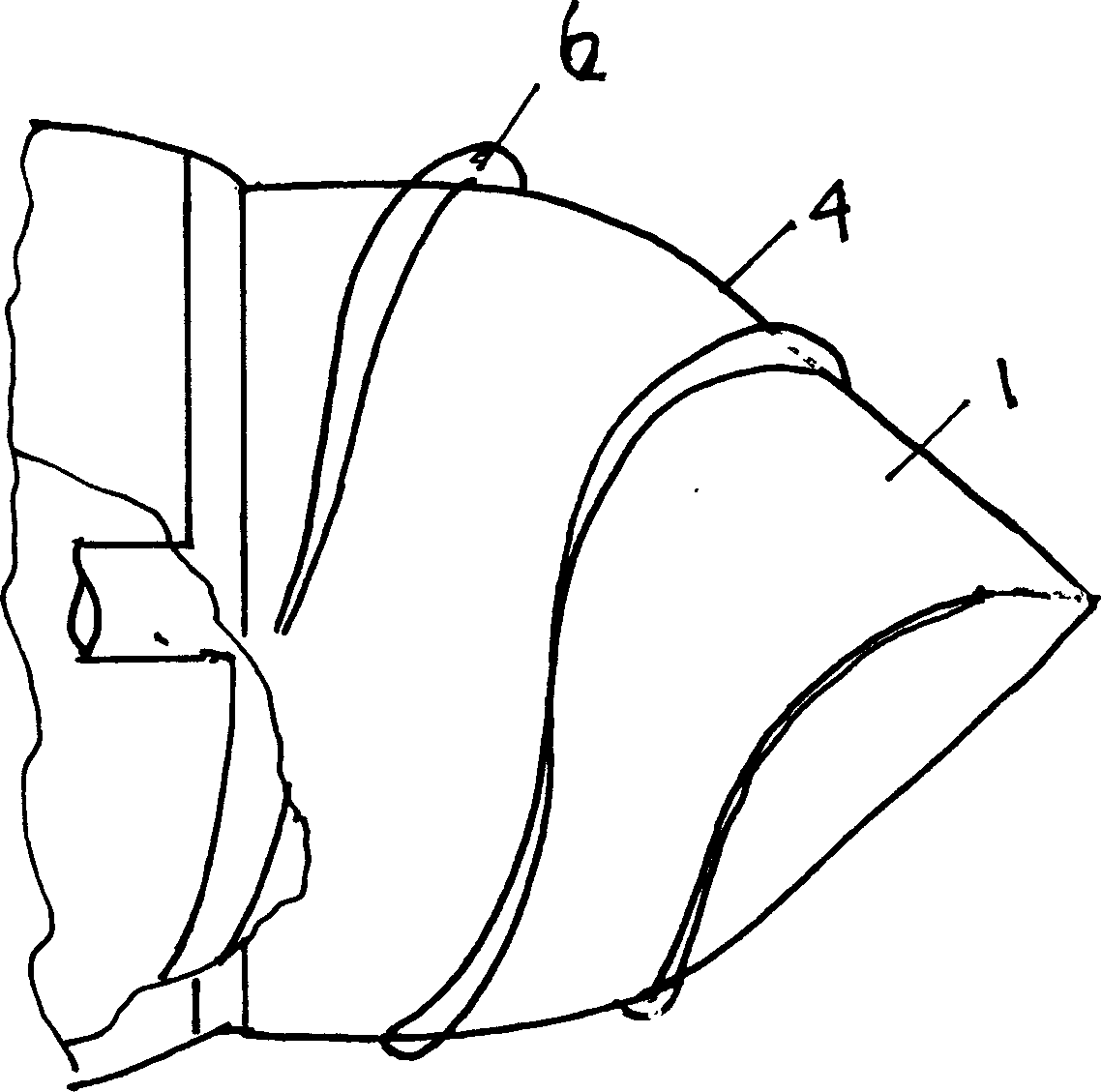
[0018] The generatrix of the approximate cone is a curve. As shown in Figures 1 and 2, the generatrix of an approximate cone is a curve 3 recessed into the cone. Such as image 3 , 4 The other shown is that the generatrix of the approximate cone is a curve 4 protruding outside the cone.

[0019] The spiral blade is perpendicular to the surface of the cone.

[0020] Part 5 of the spiral blade on the surface of the cone starts from the tip of the cone and extends along the surface of the cone in the opposite direction of the tip; part 6 starts from the part below the tip of the cone and extends along the surface of the cone in the opposite direction to the tip of the cone. The two spiral blades are arranged alternately.

[0021] As sho...


PUM


Abstract

A flow divider for quickly splitting the water in the front of a running object in the water to increase its speed greatly features that two kinds of spiral blades are uniformly arranged on the surface of a conic body similar to a cone. Said spiral blade has a spiral curve extended from the tip of conic body. The generating line of said conic body is a concave curve and a convex curve, which are similar to the generating line of a cone. Said spiral blade has wide lower end and narrow top end.

Description

Technical field [0001] The invention belongs to a device for quickly moving objects to eliminate the oncoming fluid resistance, and particularly relates to a shunt. Background technique [0002] At present, rockets are mainly launched through the atmosphere, while artillery shells and bullets are driven by penetrating force in the air. Because the air has low density and elasticity (compressible), the resistance is small and the range is far, but in water it is not. Because of the high density and inelasticity (incompressible), it is impossible for objects to travel far in the water by means of penetrating force. And it is difficult to achieve high speeds. Summary of the invention [0003] The technical problem to be solved by the present invention is to provide a shunt. To further increase the speed of objects moving in the water, in addition to increasing the squeezing force to the front, the water before the movement is quickly drained, and the force of discharging is increas...

Claims


Application Information

Patent Timeline
IPC IPC(8): B63B3/46
Inventor 冯永刚
Owner 冯永刚
Learn More