
Heater controller of drier

A control device and heating device technology, which is applied in the direction of dryers, drying, lighting and heating equipment, etc., can solve the problems of unable to adjust the output power of the heater, increase the production cost, and unreasonable structure of the heat sink, so as to reduce production Effects of cost reduction, area reduction, and improvement in power usage efficiency

Inactive Publication Date: 2004-07-07
LG ELECTRONICS (TIANJIN) APPLIANCES CO LTD
View PDF0 Cites 4 Cited by
  • Summary
  • Abstract
  • Description
  • Claims
  • Application Information

AI Technical Summary

Problems solved by technology

[0019] In the existing dryers, the heater with a delayer cannot adjust the output power of the heater, and the heater with a triac is unreasonable in structure to solve the problem of heat dissipation. and increase production costs

Method used


Image

  • Heater controller of drier
  • Heater controller of drier
  • Heater controller of drier

Examples


Embodiment Construction

[0043] Hereinafter, the dryer designed in the present invention will be described in detail with reference to the accompanying drawings.

[0044] image 3 and Figure 4 It is the structural diagram of the dryer designed by the invention.

[0045] Depend on image 3 , Figure 4 As shown, the casing 53 constitutes the appearance of the dryer. And the front panel 41 forming the front part of the dryer is provided at the head end of the casing 53 . Inside the cabinet 53, the drum 44 that dries the laundry while rotating is provided. The drum 44 is driven to rotate by a drum driving belt 54 wound around its periphery. An exhaust port 43 opening to the inside of the drum 44 is formed on the inner surface of the front panel 41 . The main function of the exhaust port 43 is to discharge the air inside the cylinder 44, and a linen filter 36 for removing impurities in the air is provided at its entrance.

[0046] An electrode sensor 38 for detecting the dryness of the laundry ins...


PUM


Abstract

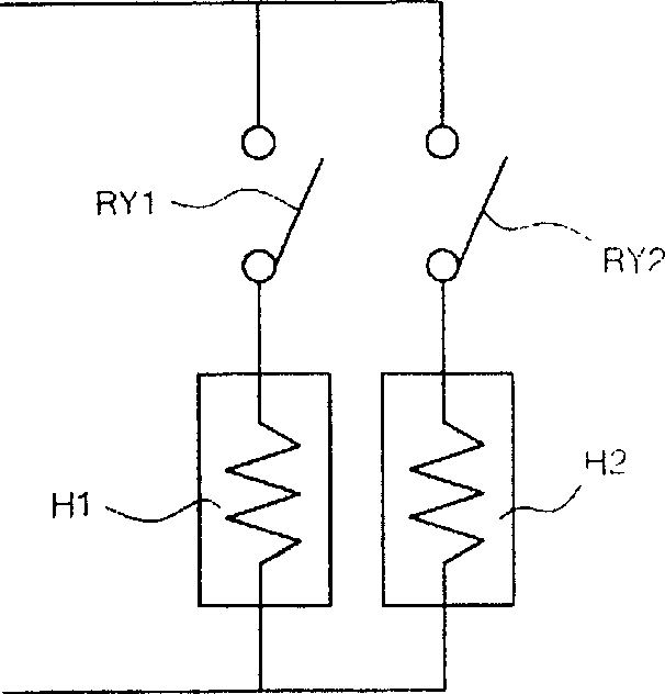
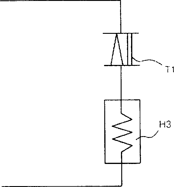
A heater controller of baker has two or more heaters for supplying hot air to drum, a power fixing switch element connected to one of heater to make the heater output fixed power, a power variable switch element connected to another heater for making the heater output adjustable power, and the control element for said two switch elements. The three-terminal bidirectional SCR switch is used to control the 50% of heater power, so simplifying the structure of radiator and lowering cost.

Description

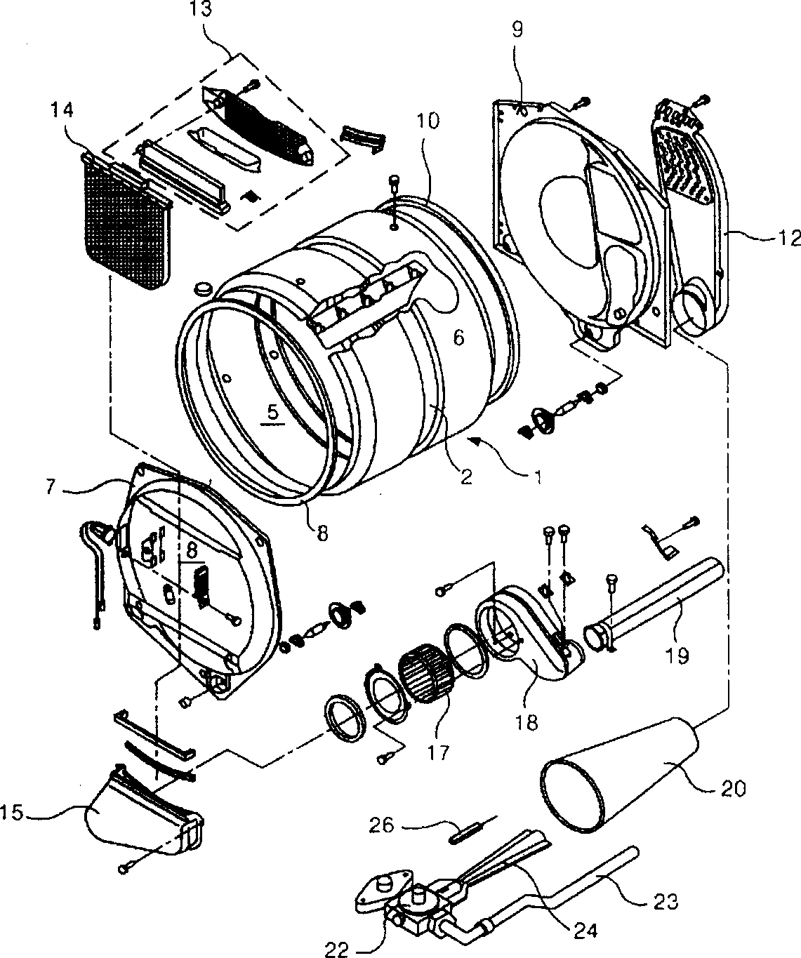
technical field [0001] The invention relates to a dryer, in particular to a heater control device of the dryer which can adjust the output power of the heater. Background technique [0002] figure 1 An exploded oblique view of the main structure of the dryer showing the general technical design. It can be seen from the figure that the drum 1 is arranged in the casing (not shown in the figure) forming the appearance of the dryer. Both sides of the cylindrical drum 1 are open, and a belt groove 2 around which a conveyor belt (not shown) driven by a separate driving source is wound is formed along the middle of the outer cylindrical surface of the drum 1 . A drying box 5 is formed inside the drum 1 . A plurality of baffles 6 are formed inside the drying box 5 to stir the object to be dried when the drying box 5 rotates. [0003] A front cover 7 and a rear cover 9 are respectively arranged at the head end and the rear end of the drum 1 . The main function of the front cover...

Claims


Application Information

Patent Timeline
Patent Type & Authority Applications(China)
IPC IPC(8): F26B17/32
Inventor 金相斗郑成海
Owner LG ELECTRONICS (TIANJIN) APPLIANCES CO LTD
Learn More