Traction continuously variable transmission device, split-power transmission system and apparatus using same

A technology of transmission system and transmission device, which is applied in the direction of transmission device, friction transmission device, mechanical equipment, etc., and can solve problems such as design restrictions, application restrictions, PSTS difficulties, etc.

Inactive Publication Date: 2004-07-07
朴鲁吉
View PDF0 Cites 3 Cited by
  • Summary
  • Abstract
  • Description
  • Claims
  • Application Information

AI Technical Summary

Problems solved by technology

Due to this, the application of simple PGU is limited
Also, for a PSTS using two PGUs, the power source and load are connected to the connection point of PGU1 and PGU2, and the transmission is only connected to the unconnected connection element, which results in a very limited design
Therefore, it is very difficult to design a PSTS with a varying structure that meets various speed requirements from a conventional PSTS using two PGUs

Method used


Image

  • Traction continuously variable transmission device, split-power transmission system and apparatus using same
  • Traction continuously variable transmission device, split-power transmission system and apparatus using same
  • Traction continuously variable transmission device, split-power transmission system and apparatus using same

Examples


Embodiment Construction

[0028] Hereinafter, preferred embodiments of the present invention will be described in detail with reference to the accompanying drawings.

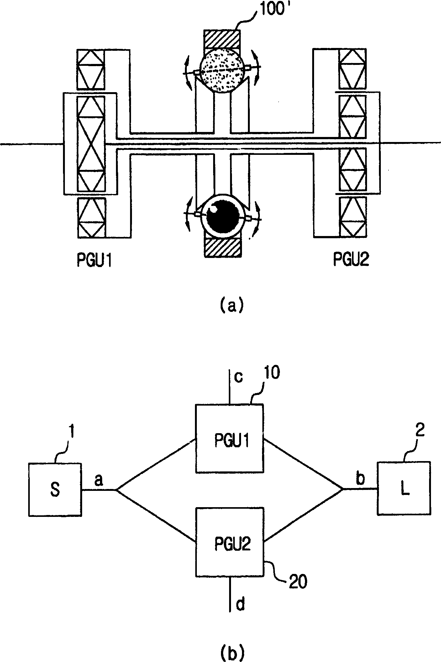
[0029] Figures 1 to 3 It has been explained when describing the prior art. Figures 4 to 13 Description A traction drive continuously variable transmission (CVT) using a four bar crank mechanism and spherical rotors according to one aspect of the invention. A traction drive CVT apparatus using a spherical rotor (friction wheel) in which one spherical surface contacts the other spherical surface will be described below, but the present invention is not limited to this embodiment. It should be pointed out that, according to the present invention, it is possible to configure a counter-rotating rotor assembly, that is, relying on the driving rotor and driven rotor of the four-bar crank mechanism, using friction wheels instead of spherical rotors, these friction wheels have various types of contact surfaces, For example, typical flat frict...


PUM


Abstract

A continuously-variable transmission device, a power split transmission system and an apparatus using either this device or system, wherein the power input to the transmission device is transmitted to a spherical rotor at an inpit side; the spherical rotor at the input side contacts with a spherical rotor configured on one end of a counter rotor assembly, and thereby rotational driving is achieved; a spherical rotor configured in the other end of a counter rotor assembly contacts with a spherical rotor at an output side and thereby rotational driving is achieved; and locations of the counter rotor assembly are adjusted by means of a quadric crank mechanism. The transmission can be configured to comprise a power split means for splitting input power into a plurality of paths, transmitting and outputting the power, using at least one planetary gear unit (PGU), and a transmission means for receiving a part of the split power from the power split means, converting its rotational force transmitting it back to the power split means, so that the power transmitted through the transmission means can be minimized to a size required for speed change.

Description

technical field [0001] The present invention relates to a traction drive continuously variable transmission device, a power distribution transmission system and equipment using the device and system, in particular to a continuously variable unit (CVU) with a four-bar crank mechanism and a ball; a A transmission system comprising means for distributing and transmitting power utilizing at least one planetary gear unit of various types; a transmission system in which a continuously variable unit and power distribution means are combined; a system utilizing the above equipment such as bicycles, sports equipment, automobiles, toys, robots, and other similar devices. Background technique [0002] Generally, conventional transmissions, variators (V), are divided into step variable units (SVU) and continuously variable units (CVU). For the SVU, there is a gear machine and a chain machine structure at this point. For CVUs, there are various configurations of traction drive mechanis...

Claims


Application Information

Patent Timeline
Patent Type & Authority Applications(China)
IPC IPC(8): F16H15/26F16H15/28F16H15/30F16H37/08
CPCF16H2037/102F16H37/084F16H15/28F16H37/10F16H15/26F16H15/30
Inventor 朴鲁吉
Owner 朴鲁吉
Why Eureka
Try Eureka