Filter press

A technology of filter press and filter plate, which is applied in the field of filter press, and can solve difficult problems such as large-scale and multi-chamber filter press

Inactive Publication Date: 2004-07-14
ISHIGAKI CO LTD
View PDF2 Cites 16 Cited by
  • Summary
  • Abstract
  • Description
  • Claims
  • Application Information

AI Technical Summary

Problems solved by technology

The replacement of damaged filter cloth must be carried out on all the ring-shaped filter cloths hanging on the filter press, which is a very difficult job
[0006] In addition, in this filter press, since the clamping cylinder is also used to open and close the filter

Method used


Image

  • Filter press
  • Filter press
  • Filter press

Examples


Example Embodiment

[0044] Embodiments of the present invention will be described in detail below using the drawings.

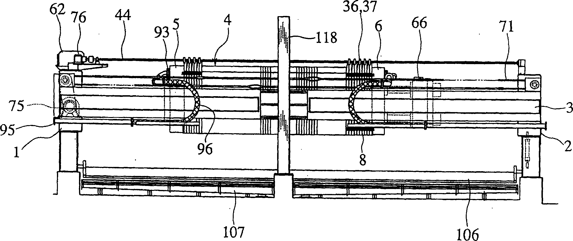
[0045] like figure 1 As shown, many side-by-side filter plates 4 are supported on a pair of parallel steel rails 3 bridged on the front frame 1 and the rear frame 2 . The front end and the rear end of the steel rail 3 are fixed on the sides of the front support 1 and the rear support 2 respectively, and the middle part is supported on the middle steel rail frame 118 .

[0046] The front movable head 5 is arranged in front of the frontmost filter plate 4 , and the rear movable head 6 is arranged behind the rearmost filter plate 4 .

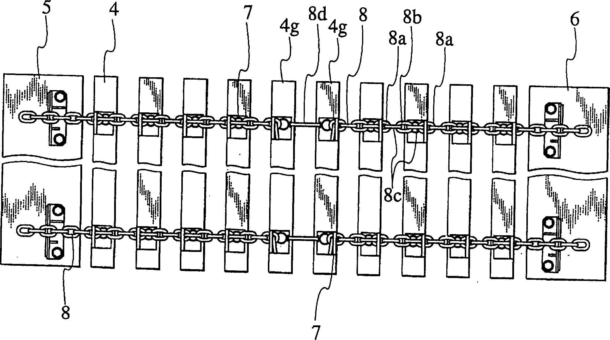
[0047] like figure 2 As shown, the filter plate 4 juxtaposed on the rail 3, the movable head 5 at the front and the movable head 6 at the rear are fixed on the locking parts 7 arranged in the upper and lower parts of the respective side walls. The endless chains, ie the moving chains 8, are connected to one another. In order to keep the interval...


PUM


Abstract

The present invention relates to press filter and is especially one press filter with several filter boards capable of being opened simultaneously to move filter cloths simultaneously to drain filter cakes and clean filter cloths. The press filter has two, one front and one back, supports, filter boards set on the steel tracks between the two supports, filter cloths set on the filter boards to form filtering chamber and connected via moving chains for opening and closing freely, upper and lower filter cloth fixing metal cores with original liquid passing hole in proper position.

Description

technical field [0001] The present invention relates to a filter press, in particular to a filter press which allows a plurality of parallel filter plates to be opened simultaneously, and filter cloth stretched between each filter plate to move simultaneously to discharge agglomerates and clean the filter cloth. Background technique [0002] Japanese Patent Laid-Open No. 11-19414 discloses a sequential plate-opening filter press, in which the upper end of the filter cloth fixed on the filter plate can be vibrated on the filter cloth support device, and when the agglomerates are discharged, Sequentially open one filter plate at a time to vibrate the filter cloth or filter plate to peel off the agglomerates from the filter cloth. [0003] In this filter press, since the center part of the filter cloth is fixed to the filter plate, even if washing water is sprayed on the filter cloth surface, there may remain agglomerates at the fixed part of the filter cloth and the filter pla...

Claims


Application Information

Patent Timeline
IPC IPC(8): B01D25/12B01D25/21
Inventor 石垣真
Owner ISHIGAKI CO LTD
Why Eureka
Try Eureka