Coaxle electric connector

An electrical connector, coaxial technology, applied in the direction of conductive connection, connection, two-pole connection, etc., can solve the problems of reducing the contact function of the connector, reducing the height, entering the gap, etc., to avoid the entry of molten solder, etc. The effect of improving the holding force and engaging force, and improving the holding force

Active Publication Date: 2004-07-14
HIROSE ELECTRIC GROUP
View PDF1 Cites 8 Cited by
  • Summary
  • Abstract
  • Description
  • Claims
  • Application Information

AI Technical Summary

Problems solved by technology

It will also happen that molten solder or the like tends to enter the gap from both edge portions in the width direction of the above-mentioned connecting portion, and the molten solder or the like that enters the gap may even reach the contact portion 54.
In this case, the contact function with the counterpart connector will be reduced
[0009] Especially this kind of connector is required to reduce the height, so the bottom wall of the above-mentioned medium is thinner, the strength is lower, and it is easy to be displaced due to external force and thermal expansion, so the above-mentioned gap is especially prone to occur

Method used


Image

  • Coaxle electric connector
  • Coaxle electric connector
  • Coaxle electric connector

Examples


Embodiment Construction

[0041] The following according to Figure 1 to Figure 15 , to describe the embodiment of the present invention.

[0042]

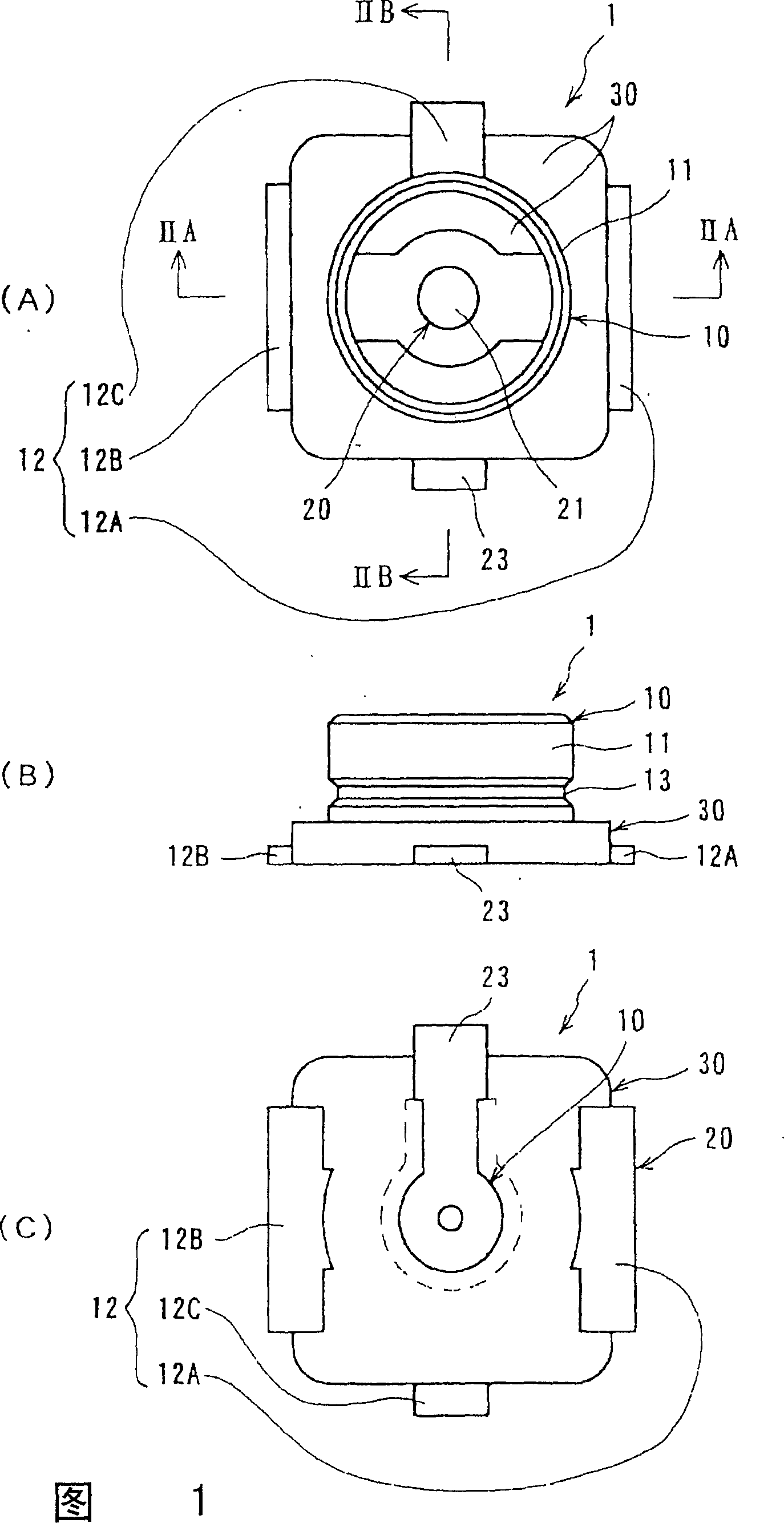
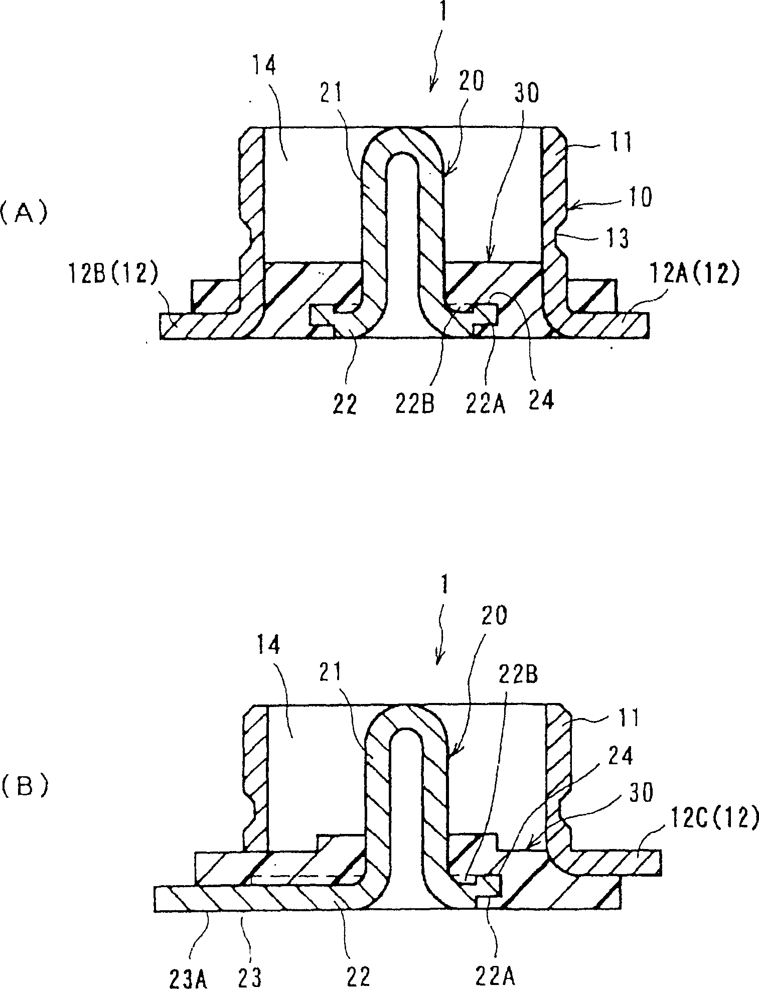
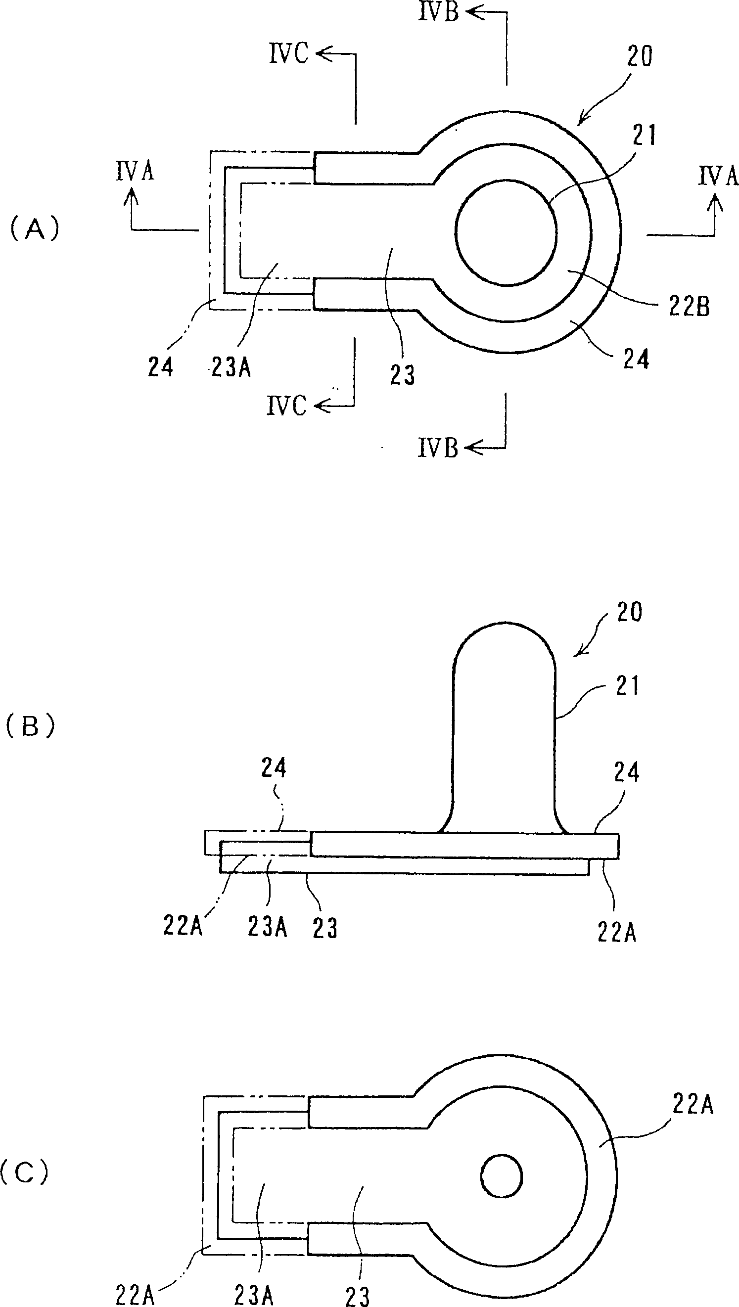
[0043] Figure 1 and figure 2 The coaxial connector 1 according to the first embodiment shown integrally holds the outer conductor 10 and the central conductor 20 via the medium 30 .

[0044]The outer conductor 10 has: a cylindrical cylindrical portion 11 having an axis in the mating direction with the counterpart connector; a leg portion 12 extending radially outward from the lower portion of the cylindrical portion 11, and is formed by placing a metal plate Formed by bending and forming. In this embodiment, the cylindrical portion 11 has a cylindrical shape, and a locking groove 13 is formed on the outer surface for locking with an external conductor of a counterpart connector (not shown) to prevent falling off. Also, the leg portion 12 is composed of leg portions 12A, 12B, and 12C extending from three positions in the circumferential direction of t...


PUM


Abstract

A coaxial electrical connector comprises an outer conductor (10) having a tubular section (11); a central conductor (20) having a contact section (21) extending in the axial direction in the tubular section (11); and a dielectric block (30) molded to hold together both the conductors (10, 20). The central conductor (20) has a radial section (22) extending outwardly in the radial direction from the bottom of the contact section (21) and a connection portion (23A) on the bottom face of the radial section (22) for contact with a circuit board. The central conductor 20 has a surface-processed portion so as to form at least one of a raised portion (24) and an indented portion (22A) and is in contact with the dielectric block at the surface-processed portion.

Description

technical field [0001] The invention relates to a coaxial electrical connector. Background technique [0002] As such a connector, a receptacle for a coaxial connector disclosed in Patent Document 1 is known. [0003] This connector is as Figure 16 As shown in (A) and (B), a cylindrical outer conductor 52 and a center conductor 53 are provided. The aforementioned cylindrical outer conductor 52 is in surface contact with the inner surface of the concave part of the medium 51 having a square shape, and on the surface including the axis. The cross-sectional shape is roughly S-shaped; the central conductor 53 has a hub-shaped contact portion 54 in the center, and the contact portion 54 extends upward from the bottom surface into the aforementioned concave portion along the axis direction. [0004] The center conductor 53 has a connection portion 55 integral with the contact portion 54 . This connecting portion 55 is to extend toward radial direction in a part of circumferenti...

Claims


Application Information

Patent Timeline
Patent Type & Authority Applications(China)
IPC IPC(8): H01R4/02H01R43/02
CPCY10S439/944H01R4/023H01R24/50H01R43/0256H01R2103/00H01R43/0235
Inventor 山根雅浩
Owner HIROSE ELECTRIC GROUP
Why Eureka
Try Eureka