

Device and method for supplying molten metal of die casting machine and casting ladle
A die-casting machine and ladle technology, used in casting equipment, equipment for supplying molten metal, manufacturing tools, etc., can solve the problems of being easily damaged, heated, and shorten the life of the sleeve, and achieve the effect of preventing heat and expanding the pouring range.
- Summary
- Abstract
- Description
- Claims
- Application Information
AI Technical Summary
Problems solved by technology
Method used
Image

Examples
no. 1 example
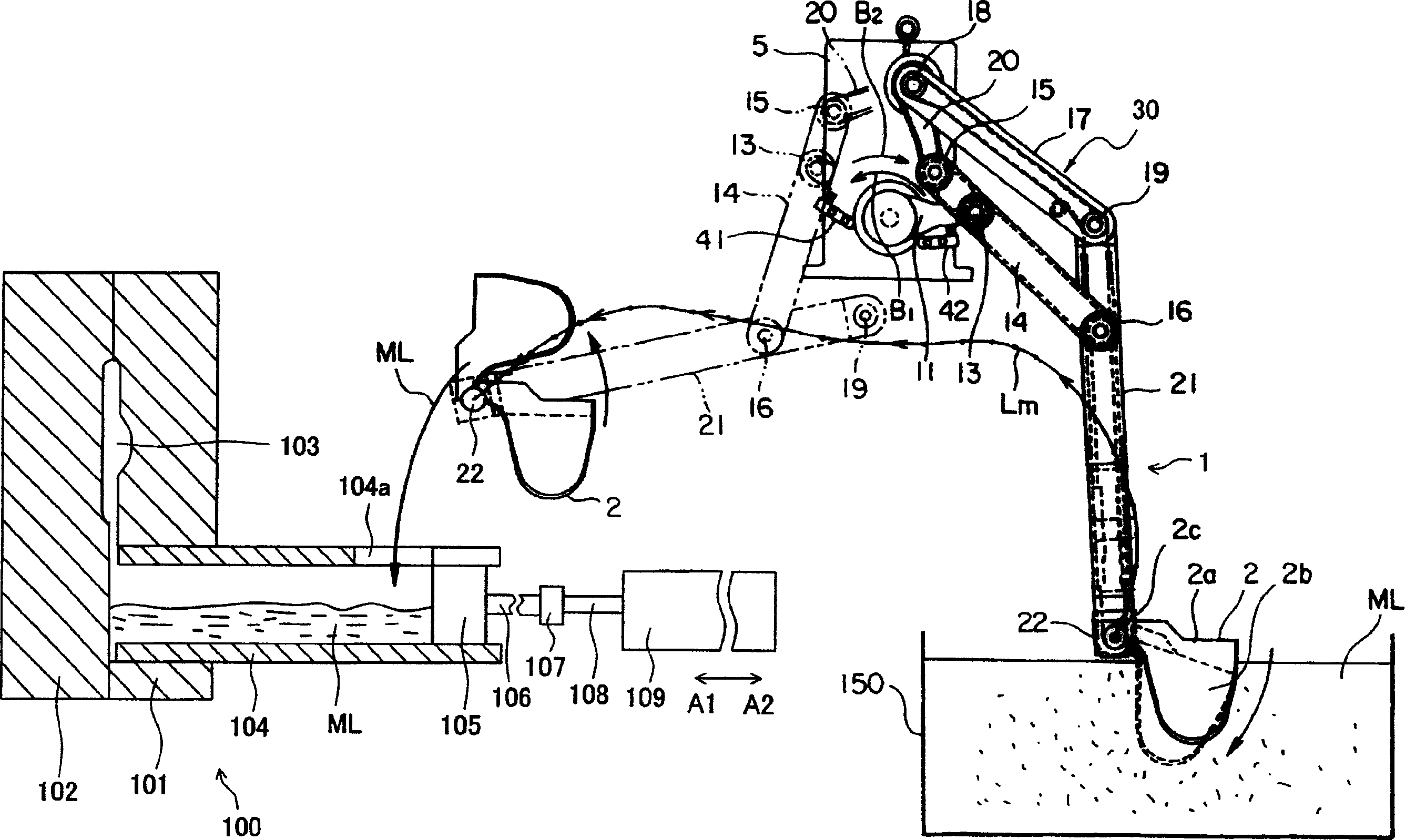
[0028] figure 1 It is a configuration diagram showing a melt supply device and a die casting machine according to an embodiment of the present invention.
[0029] exist figure 1 The medium die casting machine 100 is composed of a fixed mold 101, a movable mold 102, a sleeve 104, a plunger 105, an injection cylinder 109, and the like.
[0030] The fixed mold 101 is fixed by the fixed template of the mold fixture not shown in the figure,
[0031] The moving mold 102 is fixed by a moving platen of a mold fixing device not shown in the figure.
[0032] The fixed mold 101 and the movable mold 102 complete mold opening and closing and mold fixing through a clamping device not shown in the figure, and a mold cavity 103 is formed between the fixed mold 101 and the movable mold 102 . The mold cavity 103 communicates with the sleeve 104 .
[0033] The sleeve 104 is, for example, a cylindrical member formed of a metal material or the like, and is provided on the fixed die 101 at one ...
no. 2 example
[0078] Next, a melt supply device according to another embodiment of the present invention will be described.
[0079] The melt supply device of this embodiment has a conveying device and a ladle, and its basic structure is the same as that of the first embodiment, so the different components will be described below.
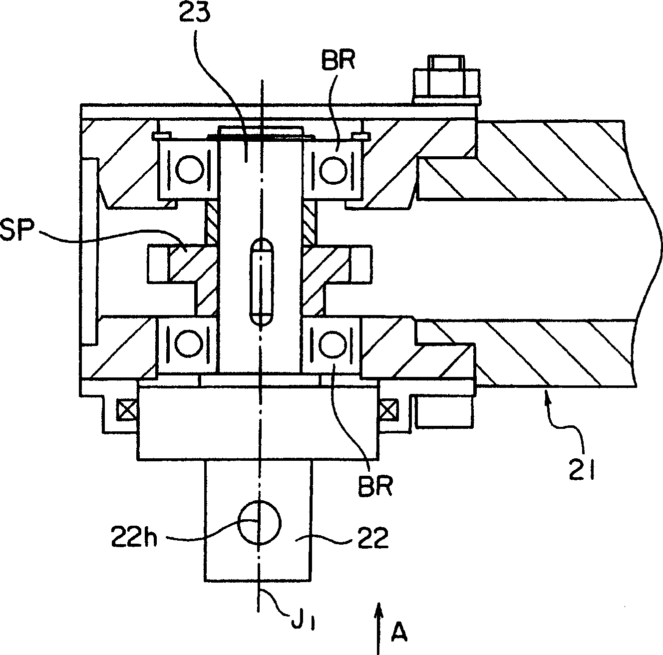
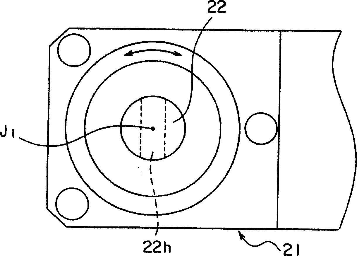
[0080] Figure 7A is a cross-sectional view along the longitudinal direction of the front end of the fifth arm 21A of the conveying device of this embodiment, Figure 7B From Figure 7A The side view seen from the A direction.
[0081] As shown in FIG. 7 , a flange portion 24 is formed at one end of the rotating shaft 23 , and the mounting shaft 22 is formed on the flange portion 24 . A pin hole 3 k is formed in the diameter direction of the mounting shaft 22 .
[0082] As shown in FIG. 7 , the distance between the axis J1 of the rotating shaft 23 and the axis J3 of the mounting shaft 22 is Lb. That is, the axis J1 of the rotating shaft 23 is offset from th...
no. 3 example
[0092] Next, a melt supply device according to another embodiment of the present invention will be described.
[0093] In the first embodiment, the positional relationship between the rotating shaft 23 and the ladle 2 is fixed.
[0094] In this example, if Figure 10 As shown, the connection plate 25 is passed between the rotating shaft 23 (installation shaft 22) and the ladle 2, and a plurality of installation holes 25ha-25hd are provided on the connection plate 25, so that the front end 2e of the pouring port of the ladle 2 can be changed. The positional relationship with the axis J1 of the rotating shaft 23.
[0095] Specifically, attachment holes 25ha to 25hd for fitting the attachment shaft 22 are formed at four different places on the connecting plate 25 on the center circle centered on the front end portion 2e of the spout 2d of the ladle 2 .
[0096] Between the rotating shaft 23 mounting shaft 22 and the connecting holes 25ha-25hd, by rotating regularly, the moving ...
PUM
 Abstract
Description
Claims
Application Information