A urea spiral heating reaction device and its application

A reaction device and heating device technology, which is applied in chemical/physical/physical chemical fixed reactors, heat treatment, organic chemistry, etc., can solve the problem of complex process flow, low purity of reaction products and reduced equipment capacity of molten salt pyrolysis and other problems to achieve the effect of avoiding sticking to the wall, avoiding heat, and reducing energy consumption

Active Publication Date: 2017-07-07
SHANDONG UNIV
View PDF1 Cites 0 Cited by
  • Summary
  • Abstract
  • Description
  • Claims
  • Application Information

AI Technical Summary

Problems solved by technology

The molten urea produced during the heating process of the melting pyrolysis method is easy to adhere to the reactor wall and the agitator, resulting in difficulty in heat transfer, high temperature near the wall, and excessive condensation of by-products and amine derivatives. The purity is not high
Although the material return method solves the phenomenon of material sticking to the wall, it requires a large return multiple, resulting in high energy consumption and reduced equipment capacity
The molten salt pyrolysis process is complicated, consumes a lot of energy, and the conversion rate of urea is low, and the equipment is seriously corroded

Method used


Image

  • A urea spiral heating reaction device and its application
  • A urea spiral heating reaction device and its application
  • A urea spiral heating reaction device and its application

Examples


Embodiment 1

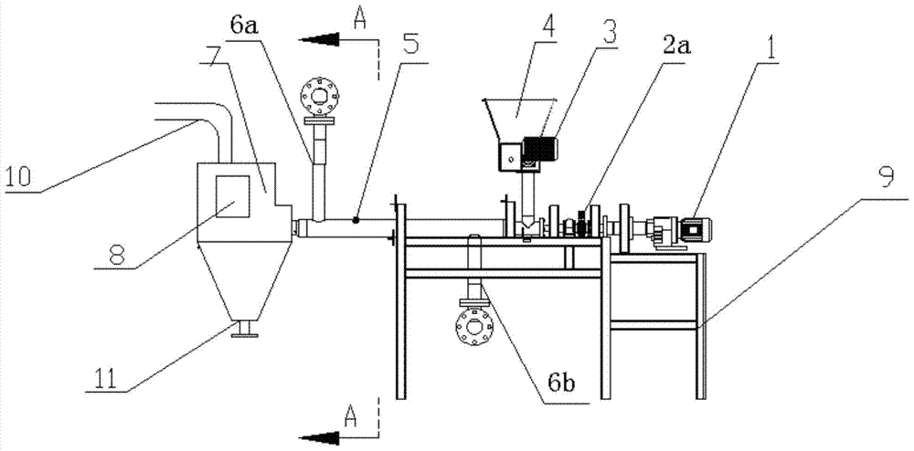
[0039] A urea spiral heating reaction device, comprising a reactor 5, a feed bin 4 and a feed bin 7, the reactor 5 is a cylindrical structure, and the feed bin 4 and the discharge bin 7 are respectively arranged on the reactor 5 ;

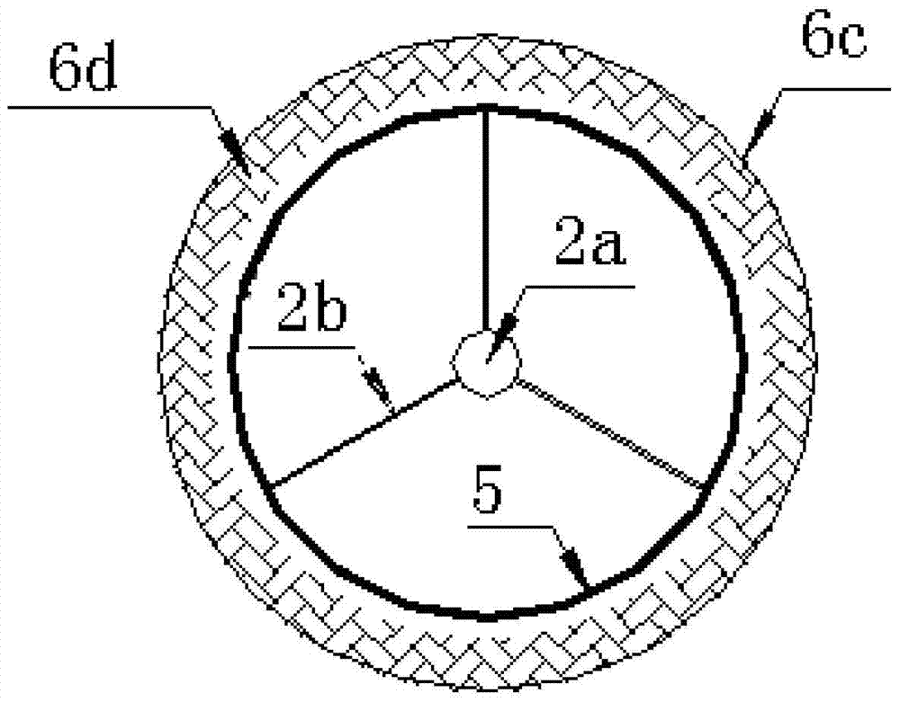
[0040] The inside of the reactor 5 is provided with a stirring shaft 2a, the surface of the stirring shaft 2a is spirally provided with fins 2b, and the stirring shaft 2a is connected with a stirring shaft motor 1;

[0041] A heating device is provided on the outside of the reactor 5, and the discharge bin 7 is provided with a gas outlet 10 and a discharge port 11;

[0042] The heating device is a jacket 6c with a thermal material 6d, and the thermal material 6d is heat-conducting oil;

[0043] The jacket 6c is provided with a hot material feed pipe 6a and a hot material discharge pipe 6b;

[0044] The distance between the fins 2b and the inner wall of the reactor 5 is 1mm;

[0045] The feed bin 4 is provided with a feed bin motor 3;

[0046] T...

Embodiment 2

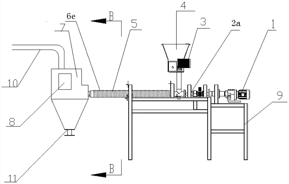
[0049] A urea spiral heating reaction device, comprising a reactor 5, a feed bin 4 and a feed bin 7, the reactor 5 is a cylindrical structure, and the feed bin 4 and the discharge bin 7 are respectively arranged on the reactor 5 ;

[0050] The inside of the reactor 5 is provided with a stirring shaft 2a, the surface of the stirring shaft 2a is spirally provided with fins 2b, and the stirring shaft 2a is connected with a stirring shaft motor 1;

[0051] A heating device is provided on the outside of the reactor 5, and the discharge bin 7 is provided with a gas outlet 10 and a discharge port 11;

[0052] The heating device is a heating wire 6e;

[0053] The distance between the fins 2b and the inner wall of the reactor 5 is 5mm;

[0054] The feed bin 4 is provided with a feed bin motor 3;

[0055] The discharge bin 7 is provided with a discharge bin endoscope 8;

[0056] The urea spiral heating reaction device further includes a support 9 on which the reactor 5 , the stirrin...

Embodiment 3

[0058] As in the urea spiral heating reaction device described in Example 1, the difference is that the heating material 6d is hot steam;

[0059] The distance between the fins 2b and the inner wall of the reactor 5 is 3mm.


PUM


Abstract

The invention relates to a spiral-heating reaction device for urea and application the spiral-heating reaction device. The spiral-heating reaction device comprises a reactor, a feeding bin and a discharging bin, wherein the reactor is of a cylinder structure, and the feeding bin and the discharging bin are respectively arranged on the reactor; a stirring shaft is arranged in the reactor, the surface of the stirring shaft is spirally provided with fins and the stirring shaft is connected with a stirring shaft motor; a heating device is arranged at the outer side of the reactor, and the discharging bin is provided with a gas outlet and a discharging opening. The spiral-heating reactor device has the advantages that materials are pushed to advance spirally by the fins spirally arranged on the stirring shaft, so that the heat transferring is uniform, the local heating for the materials and the generation of excessively-condensed side products and amine derivatives are avoided and the purity of reaction products is improved; and the fins of the stirring shaft are close to the inner wall of the reactor, so that the occurrence of the wall-sticking phenomenon in the reaction process is avoided.

Description

[0001] Technical field: [0002] The invention relates to a urea spiral heating reaction device and its application, belonging to the technical field of material heating equipment. [0003] Background technique: [0004] The production method of existing cyanuric acid is mainly urea pyrolysis. There are two types of pyrolysis methods: solid-phase method (melt method) and liquid-phase method (solvent method). The reaction equation of generating cyanuric acid is as follows: [0005] [0006] Both methods are to put solid urea into a reactor, and produce cyanuric acid by heating urea to 200-300°C with or without a catalyst, with or without a solvent. [0007] There are pros and cons to both approaches. The liquid phase method refers to suspending urea in an organic solvent, heating and polymerizing in a reactor, then removing the solvent, washing with water, and drying to obtain a high-purity product. The solvents used in the production of cyanuric acid by the solvent metho...

Claims


Application Information

Patent Timeline
Patent Type & Authority Patents(China)
IPC IPC(8): B01J6/00B01J19/18C07D251/32
CPCB01J6/00B01J19/0066B01J19/1812B01J2219/0002B01J2219/00076B01J2219/00135B01J2219/00184B01J2219/00245B01J2219/00716B01J2219/0072B01J2219/182B01J2219/1943C07D251/32
Inventor 朱维群王付燕王倩袁爱丽
Owner SHANDONG UNIV
Why Eureka
Try Eureka