
High frequency heating apparatus

a heating apparatus and high frequency technology, applied in lighting and heating apparatus, electric/magnetic/electromagnetic heating, furnaces, etc., can solve the problems of fragility, poor usability regarding process time, and glass size, and achieve rapid heating of substrates, prevent localized heating, and high frequency

Active Publication Date: 2019-10-29
SAMSUNG CORNING PRECISION MATERIALS CO LTD
View PDF28 Cites 1 Cited by
  • Summary
  • Abstract
  • Description
  • Claims
  • Application Information

AI Technical Summary

Benefits of technology

The solution achieves uniform heating of large glass substrates with improved temperature growth rates and energy efficiency, preventing localized heating and ensuring consistent substrate temperature across the entire area, including corners.

Problems solved by technology

However, the trend in glass materials towards a light and thin profile leads to a problem of fragility due to its high brittleness.
The chemical strengthening technology has the drawbacks of poor usability regarding process time necessary for the ion exchange between the glass surface and a water solution, the size of the glass, recycling of the water solution (contamination and concentration control), and the like.
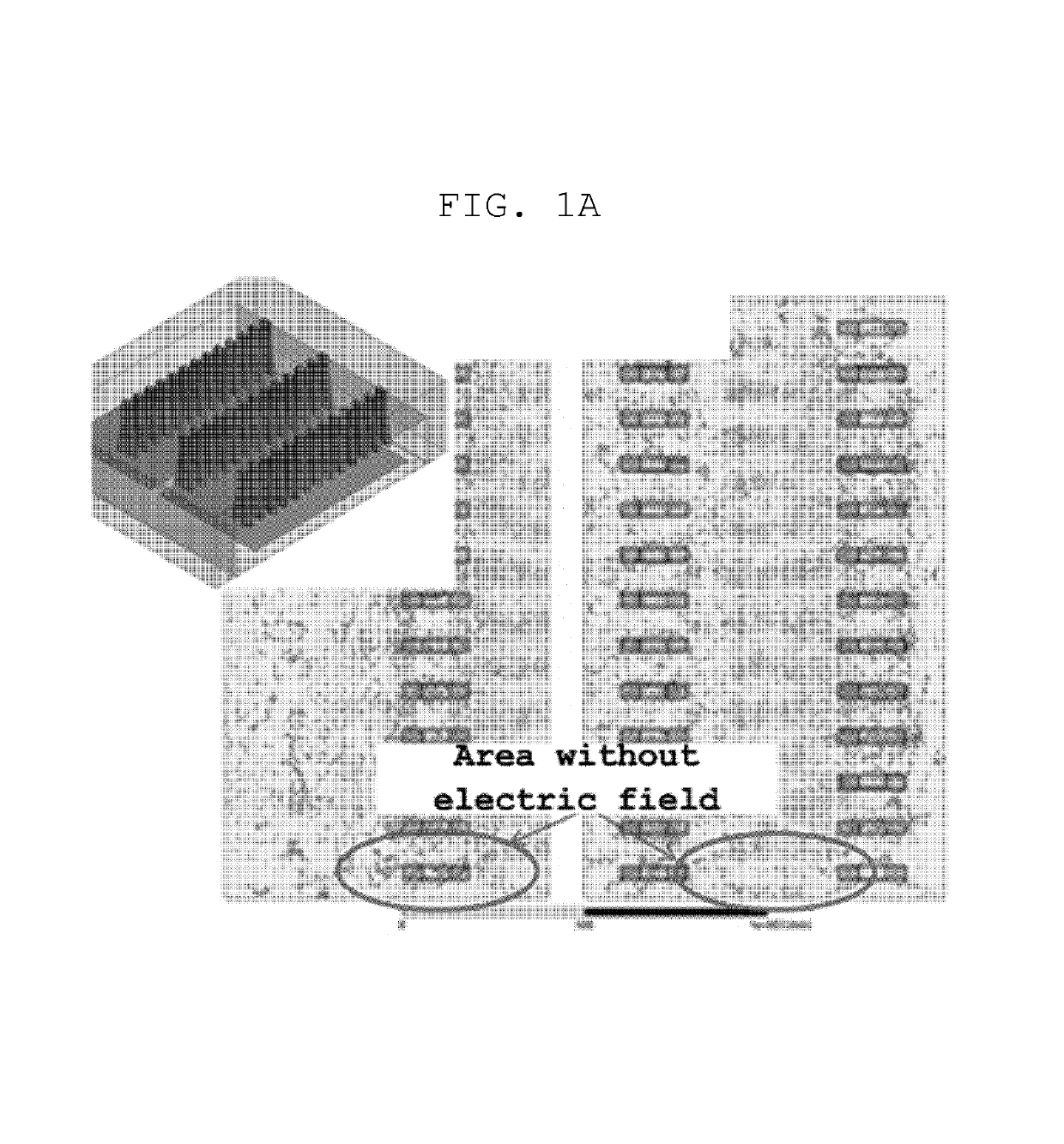
However, in the case of heat-treating a plate glass having a large size by applying the high frequency technology of the related art, the use of a single high frequency generator is disadvantageous in that control over electric field distribution inside a chamber is difficult and the temperature growth rate is low.
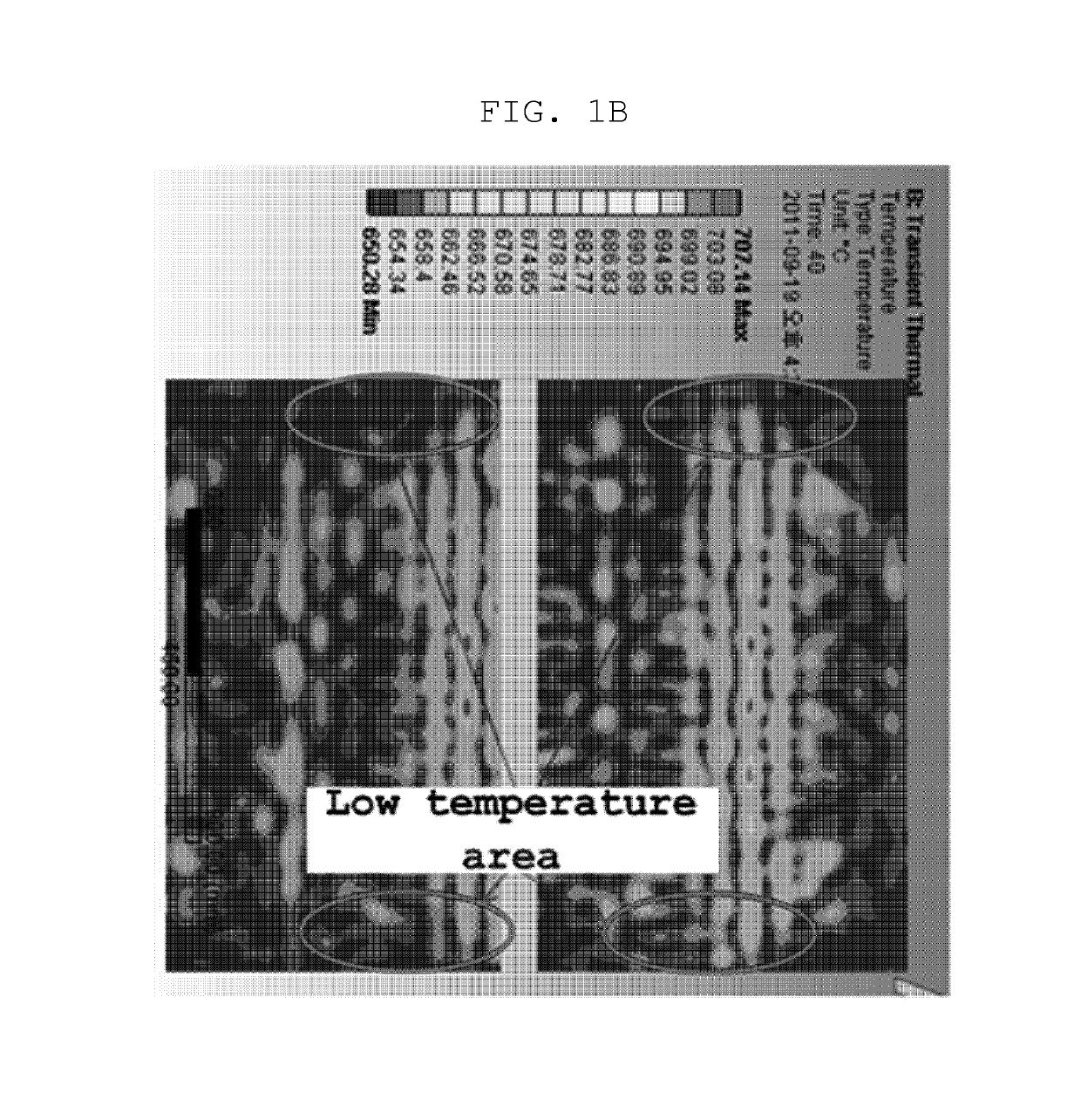
Although the use of a plurality of high frequency generators increases the temperature growth rate to a certain degree, concentration in electric fields due to interference between the high frequency generators leads to localized heating in the glass and the decreased heating efficiency, which is problematic.
In addition, hot spots are formed in localized areas of the plate glass due to the interference of the electric fields.
Accordingly, in the case of high frequency heating using a single high frequency generator, the problem is that the temperature growth rate is low.
In the case of high frequency heating using a plurality of high frequency generators, the problems are that localized heating occurs due to the interference between high frequency waves generated by the high frequency generators and the concentration in electric field although the temperature growth rate is improved to a certain degree.

Method used


Image

  • High frequency heating apparatus
  • High frequency heating apparatus
  • High frequency heating apparatus

Examples


Embodiment Construction

[0034]Reference will now be made in detail to a high frequency heating apparatus according to the present invention of the present invention, embodiments of which are illustrated in the accompanying drawings and described below, so that a person having ordinary skill in the art to which the present invention relates can easily put the present invention into practice.

[0035]Throughout this document, reference should be made to the drawings, in which the same reference numerals and signs are used throughout the different drawings to designate the same or similar components. In the following description of the present invention, detailed descriptions of known functions and components incorporated herein will be omitted when they may make the subject matter of the present invention unclear.

[0036]In addition, in the following description, a direction from the front to the rear is defined as the direction in which a substrate is carried, and a direction from left to right is defined as the...


PUM

PropertyMeasurementUnit
frequencyaaaaaaaaaa
distanceaaaaaaaaaa
diameteraaaaaaaaaa

Abstract

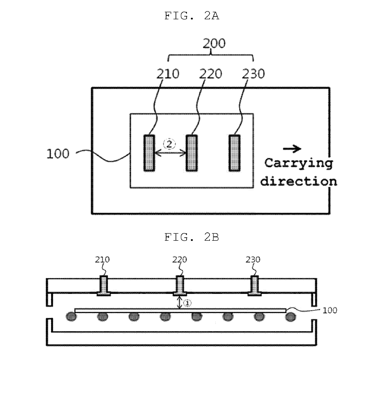
A high frequency heating apparatus which heats a substrate by applying high frequency waves thereto. The high frequency heating apparatus includes a high frequency generator which generates high frequency to heat the substrate. The distance from the substrate to the high frequency generator is n / 2*λ, where n is a natural number ranging from 1 to 6, and λ is the wavelength of the high frequency that is generated by the high frequency generator.

Description

CROSS REFERENCE TO RELATED APPLICATION[0001]The present application claims priority from Korean Patent Application Number 10-2012-0022640 filed on Mar. 6, 2012, the entire contents of which application are incorporated herein for all purposes by this reference.BACKGROUND OF THE INVENTION[0002]Field of the Invention[0003]The present invention relates to a high frequency heating apparatus, and more particularly, to a high frequency heating apparatus which heats a substrate by applying high frequency waves thereto.[0004]Description of Related Art[0005]The use of glass materials in a variety of industrial fields, specifically, as a cover for a photovoltaic cell, a flat display such as a thin-film transistor liquid crystal display (TFT-LCD), a plasma display panel (PDP) or an organic electroluminescent (EL) device, a variety of mobile electronic devices, and the like, is rapidly increasing. Accordingly, glass materials are required to have lightweight and a thin profile.[0006]However, th...

Claims


Application Information

Patent Timeline
Patent Type & Authority Patents(United States)
IPC IPC(8): H05B6/64H05B6/70H05B6/78F27B9/36F27D11/12F27D99/00C03B29/08
CPCH05B6/64F27D11/12H05B6/70H05B6/78C03B29/08F27D99/0006F27B9/36F27D2099/0026C03B5/033C03B5/235
Inventor LEE, HOIKWANYOON, KYUNGMINCHO, SEO-YEONG
Owner SAMSUNG CORNING PRECISION MATERIALS CO LTD
Learn More