Burning system

a technology of burning system and injector, which is applied in the control device of the furnace, the type of the furnace, etc., can solve the problems of low gas consumption, document not disclosed, and reduced consumption, so as to avoid local heating, avoid undesirable marks in the end product, and avoid cracking of the injector

Inactive Publication Date: 2017-10-17
HARTSCHUH SCHAUB ERNESTO ALDOLFO
View PDF32 Cites 0 Cited by
  • Summary
  • Abstract
  • Description
  • Claims
  • Application Information

AI Technical Summary

Benefits of technology

[0014]In view of the problems described and in order to overcome them, the present application proposes a system aimed at reducing in about 30% the fuel consumption in the load firing and curing processes in industrial furnaces.
[0015]Another aim of the invention is to avoid localized heating at the point where the flame forms by using flame rotation, and consequently avoiding undesirable marks in the end product and cracking of the injectors.

Problems solved by technology

These ovens, however, do not lower the gas consumption and do not even mention the use of burners.
Ovens like these are still used, but they commonly present problems, which is why this type of double pass roller oven is not built anymore.
However, this document is directed to a specific problem which occurs with roller kilns for fine products.
Furthermore, it does not aim at reducing the consumption of gas (fuel commonly used in this type of furnace).
The second important difference lies in the fact that this prior-art document does not disclose a flame “rotation”.
With the static flame, the localized temperatures are very high, leaving marks on the products and cracking the injector's gas outlet.

Method used


Image

  • Burning system
  • Burning system
  • Burning system

Examples


Embodiment Construction

[0025]The system presented herein can be better understood from the following detailed description of the figures.

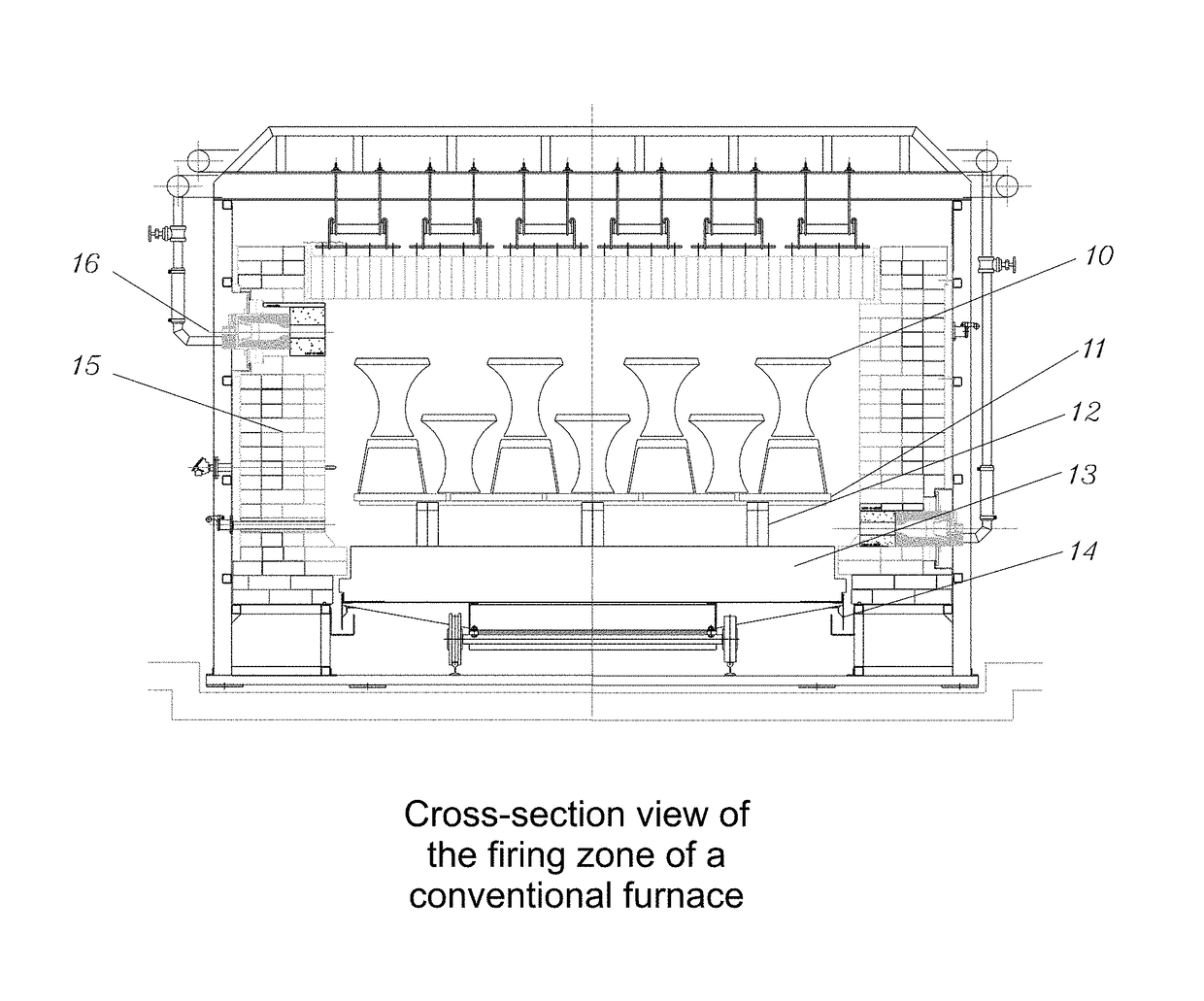
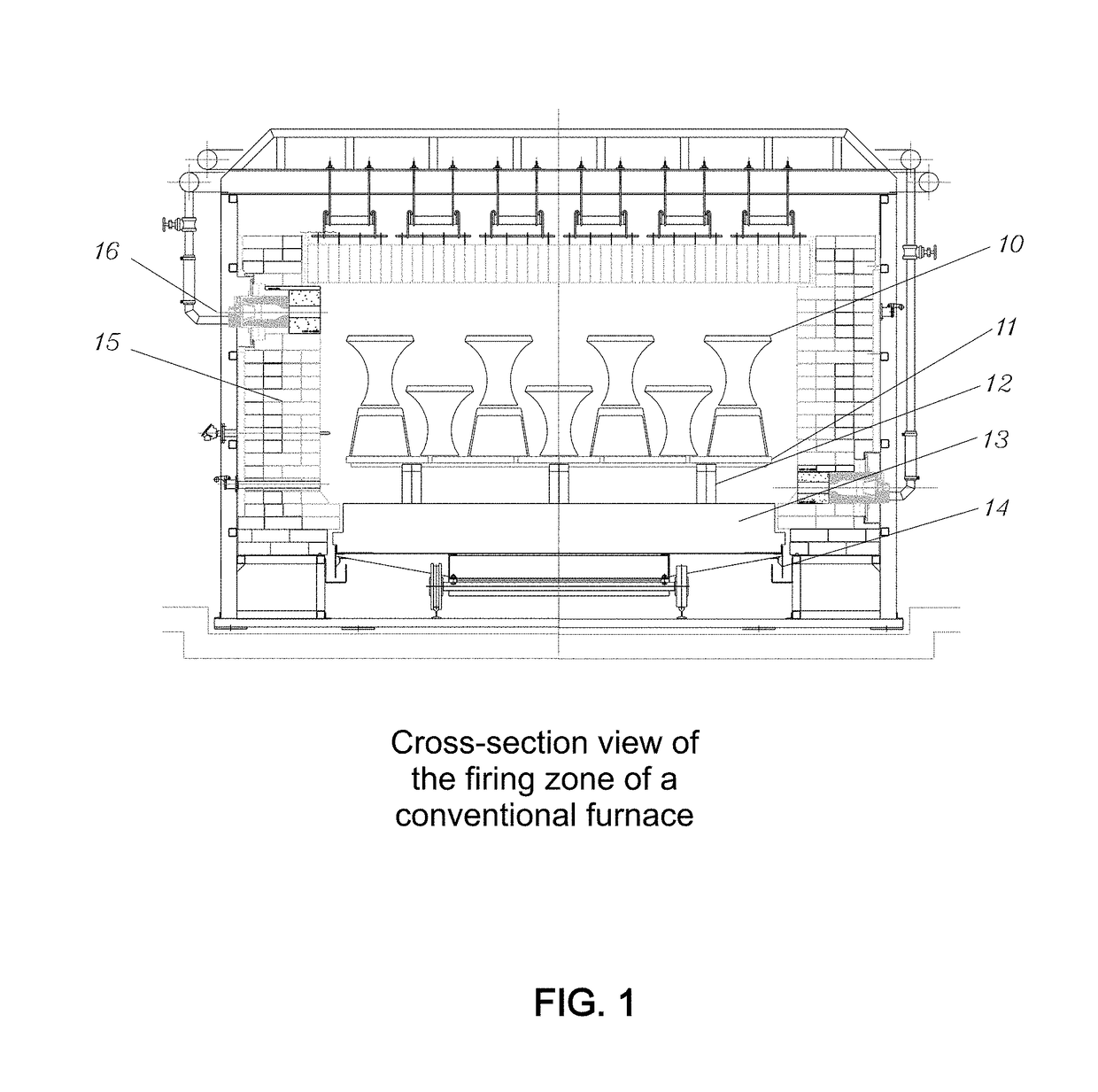
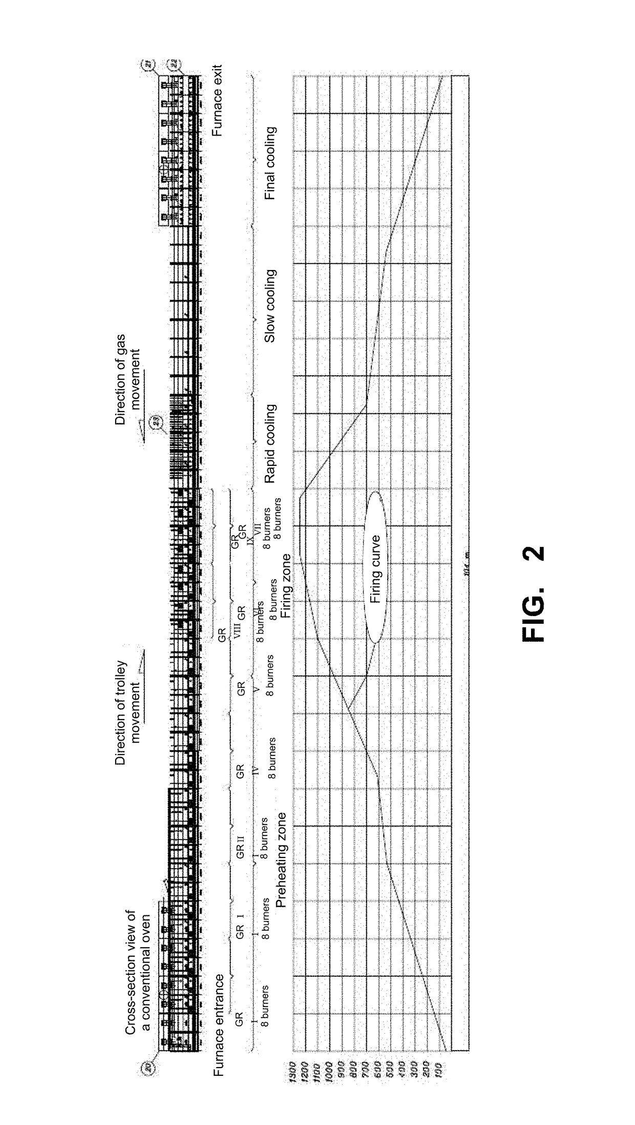
[0026]FIG. 1 illustrates a cross-sectional view of the firing zone of a conventional industrial furnace. The load 10, that is, the ceramic products, refractories etc., goes into the furnace in “raw” form, moves along inside it for hours, and comes out the opposite end, “fired”. For each product there are internal temperature curves in each section of the furnace so as to provide the material with the desired properties. As can be seen in FIG. 2, the load moves along inside the furnace and passes through different regions and temperatures. The bottom chart in FIG. 2 illustrates a typical temperature curve for sanitary materials.

[0027]The furnace has ceramic insulation 15 on the sides and on the ceiling. The thickness of said insulation 15 depends on the characteristics of the latter and on the temperature in that region. Back to FIG. 1, on the lower part of the furnace, t...


PUM

PropertyMeasurementUnit
temperaturesaaaaaaaaaa

Abstract

The present invention refers to an improved burning system for industrial furnace burners (16), more specifically for tunnel type furnaces for firing ceramic materials, to improve the thermal efficiency and reduce the consumption by these furnaces in the process of firing load (10) such as floor tiles, tiles, sanitary material, refractories, porcelain, insulators, grindstone, tableware ceramic, red ceramic and ceramic in general, by a using flame rotation system, providing a radiant flame surface by dividing the flame into smaller intermittent flames.

Description

FIELD OF THE INVENTION[0001]The present invention relates to an improved burning system in industrial furnace burners, more specifically for tunnel furnaces for burning ceramic material.DESCRIPTION OF THE PRIOR ART[0002]The tunnel type furnaces, also known as trolley furnaces, are widely known in the prior art and have been used for decades to fire ceramic products, refractories etc.[0003]These furnaces basically operate as follows: the ceramic products, refractories etc, hereinafter referred to as “load”, go into one end of the furnace in “raw” form and move along to the opposite end, where they come out “fired”. However, for each product to be fired there are different ideal internal temperature curves, subdivided in each section of the furnace, so as to provide the material with the desired structural properties. For example, for chamotte, the temperatures should be around 1000° C. For sanitary porcelain, the temperatures should be around 1200° C. Other temperatures, such as 1450...

Claims


Application Information

Patent Timeline
Patent Type & Authority Patents(United States)
IPC IPC(8): F27B9/40F27B9/36F27D3/00F27D19/00F27D99/00F27D21/00
CPCF27B9/36F27B9/40F27D19/00F27D21/00F27D99/0033
Inventor HARTSCHUH SCHAUB, ERNESTO ALDOLFO
Owner HARTSCHUH SCHAUB ERNESTO ALDOLFO
Why Eureka
Try Eureka