Internal circulation oil cylinder having built in logic valve

A logic valve and internal circulation technology, applied in the field of hydraulic cylinders, can solve the problems of reducing oil quality, consuming pressure oil energy, affecting hydraulic systems, etc., achieving the effects of compact structure, faster cylinder travel, and avoiding oil temperature rise

Inactive Publication Date: 2004-07-21
广东泓利机器有限公司
View PDF0 Cites 11 Cited by
  • Summary
  • Abstract
  • Description
  • Claims
  • Application Information

AI Technical Summary

Problems solved by technology

[0002] Existing fully hydraulic injection molding machines use multiple oil cylinders to move, close, lock, and open the mold. The logic valve of the hydraulic system controls the reciprocating movement of the oil cylinder. The two oil cylinders separated by the piston The oil in the cavity needs to flow back and forth into and out of the two oil cavities through the outer channel composed of oil ports, joints, pipes, etc. to complete the opening and closing of the mold. For injection molding machines with high precision and high speed requirements, in order to ensure the high speed locking of the mold The mold clamping cylinder must be in a high-speed operating state, and the oil in its two oil chambers must flow back and forth at high speed through the outer channel, which will increase the oil temperature, consume pressure oil energy, and even reduce oil quality, affecting the normal operation of the hydraulic system. The outer channel of the oil is prone to leakage, so higher requirements are required for the material quality, sealing performance, and flow rate of the outer channel.

Method used


Image

  • Internal circulation oil cylinder having built in logic valve
  • Internal circulation oil cylinder having built in logic valve
  • Internal circulation oil cylinder having built in logic valve

Examples


Embodiment Construction

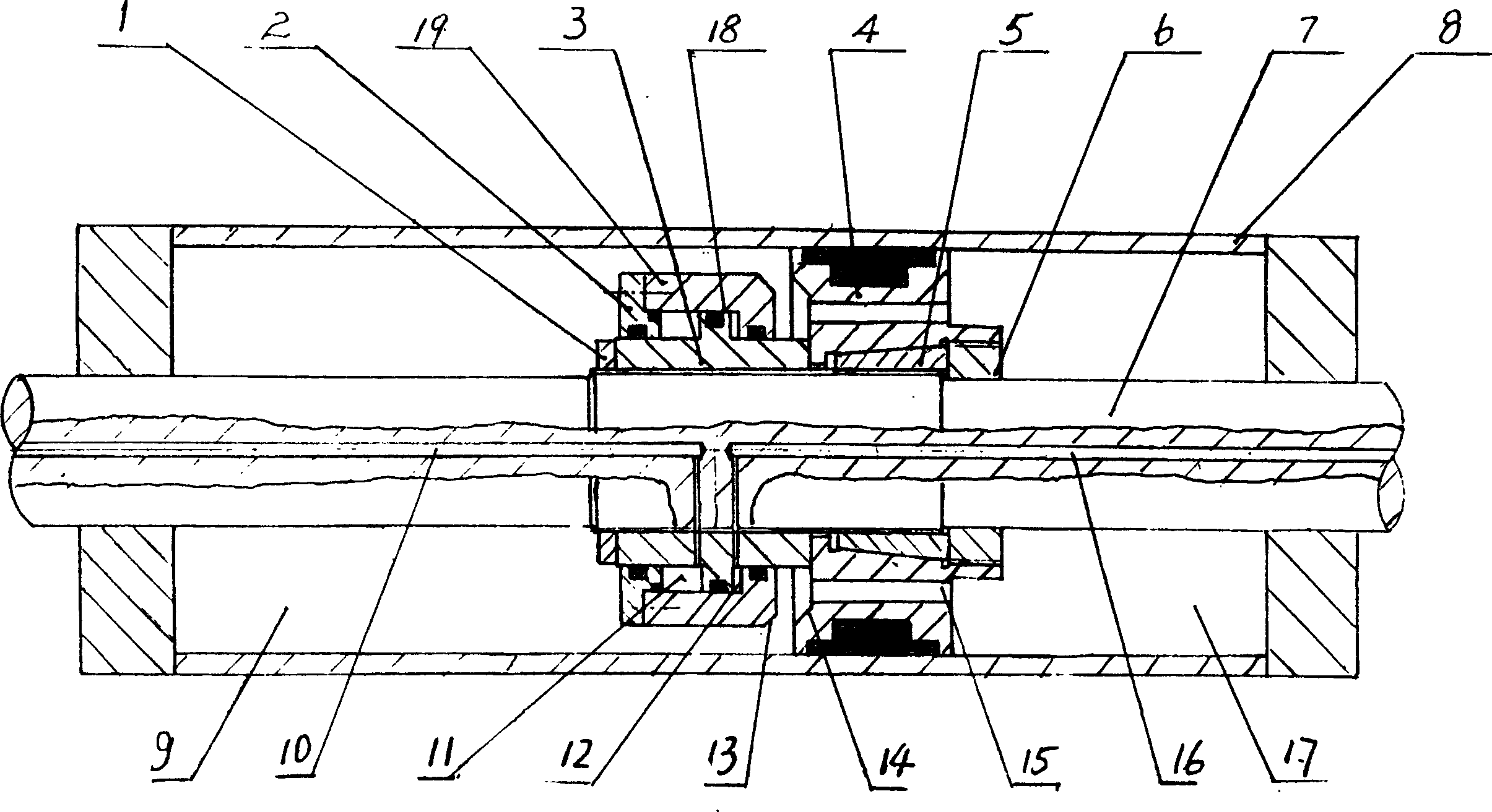
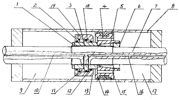
[0010] Such as figure 1 As shown, the present invention is made up of piston rod, oil cylinder, piston and logic valve, and piston 4 has axial channel 15, and piston 4 is fastened on piston rod 7 with taper sleeve 5 and self-locking nut 6, and in oil cylinder 8, is enclosed by piston 4 is divided into two oil chambers, oil chamber 9 and oil chamber 7, and the two oil chambers can communicate through the axial passage 15. The logic valve installed on the side of the piston 4 and fastened to the piston rod 7 is composed of the valve cover 2, the valve The seat 3 and the valve sleeve 19 are composed of the valve seat 3, which is threadedly connected to the piston rod 7, and positioned by the piston 4, and the nut 1 is locked, and the valve cover 2 is tightly connected with the valve sleeve 19 and moves with the valve seat 3 to form a logic The control oil chamber of the valve, the control oil chamber is divided into two control oil chambers by the pillow block 18 set on the valve...


PUM


Abstract

An internal circulation hydro-cylinder is composed of piston, hydro-cylinder, piston rod and logic valve. The piston has axial channel for two oil cavities isolated by piston rod in hydro-cylinder of guide channel, the logic valve is set on one side of the piston and closely fixed on the piston rod to make high-pressure oil go into oil control chamber of the logic valve separately through channels set on the piston rod so valve bush is pushed to move the block or open of axial channel of the piston rod as oil in two oil cavities flows forward and back ward within internal circulation. It is not necessary to set external channel for oil circulation.

Description

Technical field [0001] The invention relates to a hydraulic device, in particular to a hydraulic oil cylinder used for injection molding machines, plastic molding machines, die-casting machines and hydraulic presses. Background technique [0002] Existing fully hydraulic injection molding machines use multiple oil cylinders to move, close, lock and open the mold. The logic valve of the hydraulic system controls the reciprocating movement of the cylinders. The two oil cylinders separated by the piston The oil in the cavity needs to flow back and forth into and out of the two oil cavities through the outer channel composed of oil ports, joints, pipes, etc., to complete the opening and closing of the mold. For injection molding machines with high precision and high speed requirements, in order to ensure the high-speed locking of the mold The mold clamping cylinder must be in a high-speed operating state, and the oil in its two oil chambers must flow back and forth at high speed...

Claims


Application Information

Patent Timeline
Patent Type & Authority Applications(China)
IPC IPC(8): F15B13/02F15B15/16
Inventor 黄步明刘青平郭福泽
Owner 广东泓利机器有限公司
Why Eureka
Try Eureka