Supercharge Your Innovation With Domain-Expert AI Agents!

Low temperature valve device

A valve device, cryogenic valve technology, applied in the direction of valve device, valve operation/release device, lift valve, etc., can solve the problems of mixing, pneumatic fluid penetration, undesired mixture, etc.

Inactive Publication Date: 2004-07-21
SNECMA MOTEURS (FR)
View PDF0 Cites 8 Cited by
  • Summary
  • Abstract
  • Description
  • Claims
  • Application Information

AI Technical Summary

Problems solved by technology

Such penetration can lead to a drop in temperature inside the actuator and to unwanted mixtures inside the actuator between the control fluid and the cryogenic fluid
Similarly, there is a danger that part of the pneumatic fluid used in the actuator will penetrate into the valve body and mix with the cryogenic fluid

Method used


Image

  • Low temperature valve device
  • Low temperature valve device
  • Low temperature valve device

Examples


Embodiment Construction

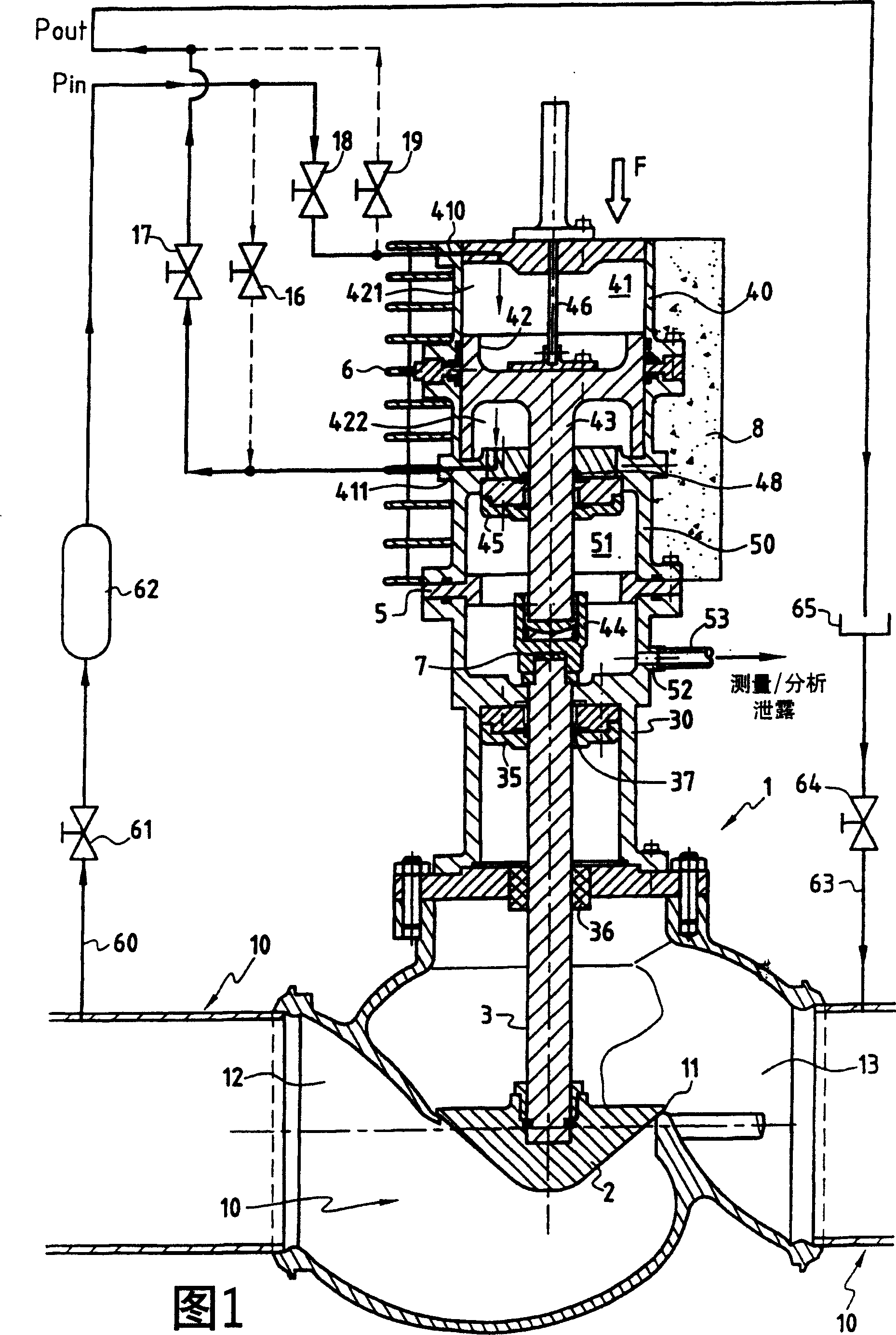
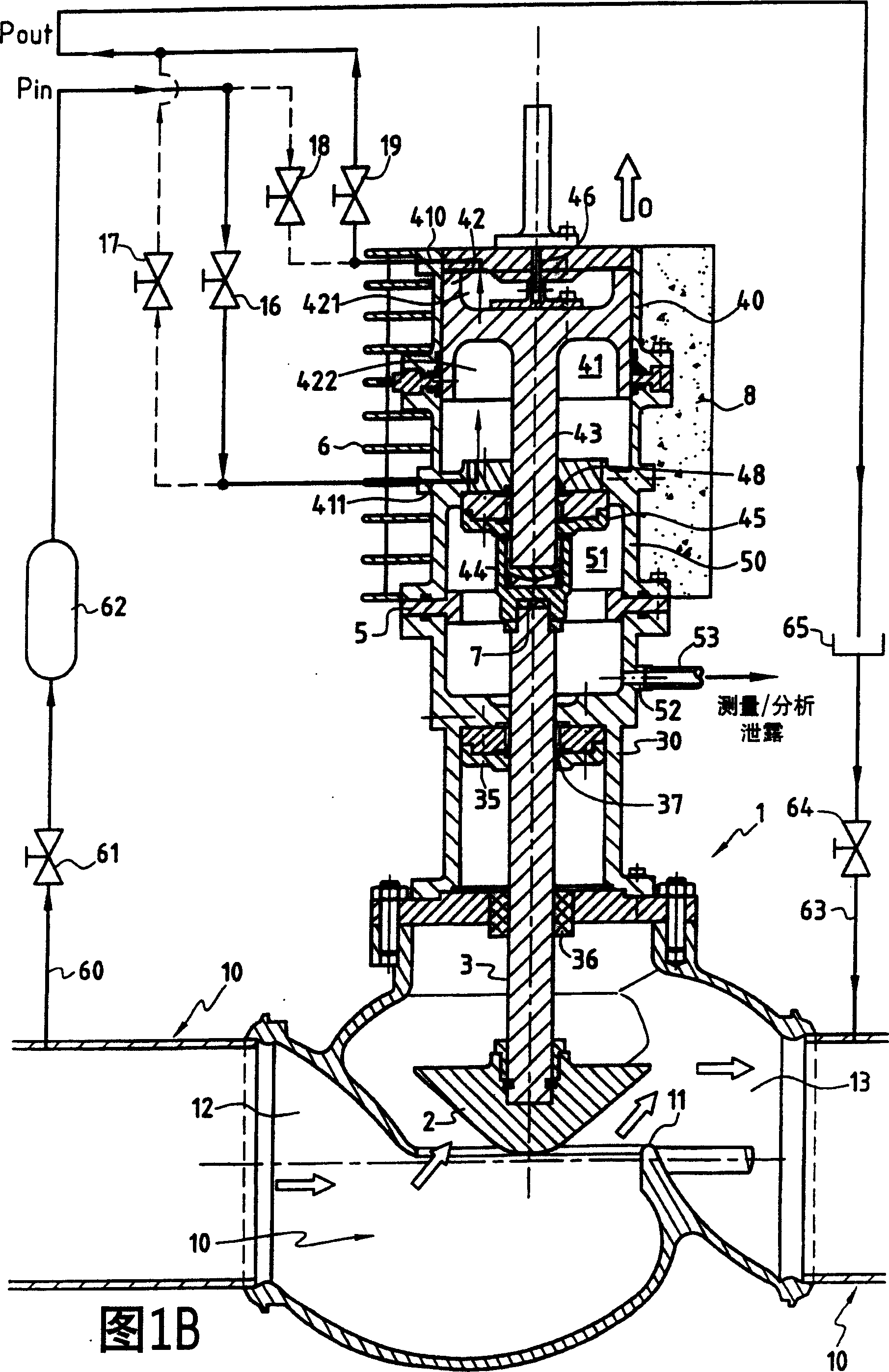
[0032] In a first embodiment of the present invention, FIG. 1A shows a valve device comprising a valve body 1 constituted by a pipe 10, and a housing 30 fixed to the upper part of the pipe in which cryogenic fluid flow. The conduit 10 comprises an upstream part 12 and a downstream part 13 separated by a valve element 2 . The valve element 2 is connected to a control rod 3 which slides vertically in guide supports 35 and 36 to move the valve element 2 between a closed position and an open position in which the valve element rests against the Formed on the pipe is a seat 11 above which the valve element is raised vertically in the open position (FIG. 1B). This will allow cryogenic fluid to flow along the pipe to be controlled.

[0033]To transmit the control movement to the control rod 3 , the valve arrangement includes a pneumatic actuator 4 . The actuator 4 is formed by a housing 40 which delimits a chamber 41 in which a piston 42 is movable.

[0034] The piston 42 defines...


PUM


Abstract

The invention provides a cryogenic valve device comprising a valve body in which a cryogenic fluid flows, and a valve member disposed in the duct and connected to a control rod for moving the valve member between a closed position and an open position so as to control the flow rate of the cryogenic fluid. The device further comprises a pneumatic actuator having a chamber containing a piston in connection with the control rod, the chamber being fed with control gas to position the piston in a determined position. The actuator is fixed to the valve body via a chamber interposed between the actuator and the valve body in such a manner as to decouple the actuator thermally from the valve body so as to maintain the temperature of the actuator, and consequently the temperature of the control gas, at a temperature that is intermediate between the temperature of the valve body and ambient temperature. The chamber is at a positive pressure so as to prevent penetration from the outside and so as to exhaust any possible leaks into the device.

Description

technical field [0001] The present invention relates to valves for controlling the flow of cryogenic fluids. The invention also relates in particular to the manufacture and implementation of pneumatic actuators operated with control gas to actuate the above-mentioned valves. Background technique [0002] The pneumatic actuator used to drive the cryogenic valve, using a control fluid such as compressed air or nitrogen, is thermally biased from the valve body, which is at said cryogenic temperature, thus ensuring that the operating temperature of the actuator remains close to ambient. In this way, by keeping the actuator close to ambient temperature, any risk of liquefaction of the control gas or formation of crystals in the actuator is avoided, so that the same type of actuator as used in non-cryogenic fluids can be used. [0003] However, in order to reduce the thermal connection between the actuator and the valve body to be controlled to a sufficient extent, and to provide...

Claims


Application Information

Patent Timeline
Patent Type & Authority Applications(China)
IPC IPC(8): F16K31/122F16K27/08F16K31/124F16K31/163F16K31/363F25B41/06
CPCF16K31/124F25B41/06F16K31/363F16K31/1635F16K27/08F16K31/122
Inventor 弗兰克·奥特莱米歇尔·克拉梅尔达米安·费热让-吕克·帕坦
Owner SNECMA MOTEURS (FR)
Features
  • R&D
  • Intellectual Property
  • Life Sciences
  • Materials
  • Tech Scout
  • Unparalleled Data Quality
  • Higher Quality Content
  • 60% Fewer Hallucinations
Learn More