Flow diagnostic system

A technology for diagnosing systems and flow, applied in variable sampling systems, flow control, general control systems, etc., to solve problems such as reducing reliability and increasing complexity

Inactive Publication Date: 2004-07-21
ROSEMOUNT INC
View PDF1 Cites 17 Cited by
  • Summary
  • Abstract
  • Description
  • Claims
  • Application Information

AI Technical Summary

Problems solved by technology

[0004] The above-mentioned known methods in the prior art all need to be equipped with static pressure sensors or need to disassemble the flowmeter, thus increasing the complexity and reducing the reliability
Also, these known methods do not provide a diagnosis of the condition of the primary element

Method used


Image

  • Flow diagnostic system
  • Flow diagnostic system
  • Flow diagnostic system

Examples


Embodiment Construction

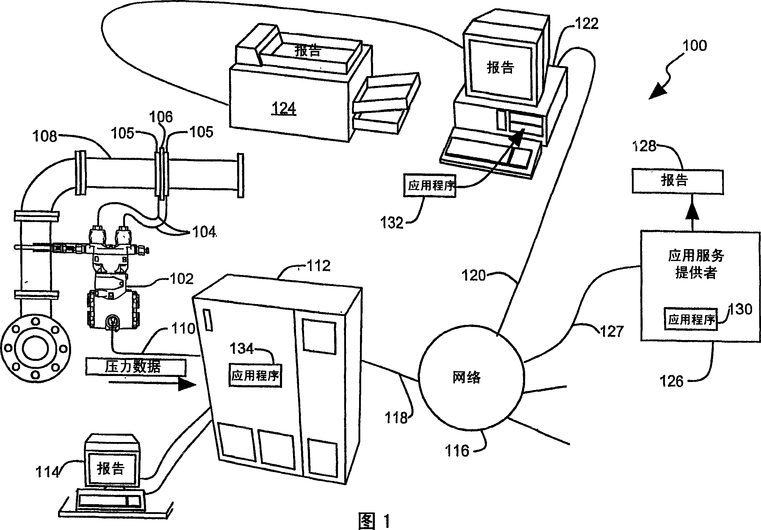
[0028] The flow diagnostic system provided by the present invention can diagnose the impulse transmission line and / or the main component connected with the pressure sensor. The diagnostic application can be downloaded from an Application Service Provider (ASP) over a network, or obtained from a computer readable medium such as a CD-ROM or diskette. Diagnostic applications can run on the control system, remote computer or ASP and provide diagnostic reports. Diagnostic applications can run on a higher-power processor than the lower-power processor built into the pressure sensor. The application of high-performance processors allows complex diagnostics to be performed in real time, providing rapid reports to plant operators on the condition of primary components, impulse transmission lines, or both. The processor built into the sensor does not require processing time for diagnostics and thus performs its measurement tasks quickly.

[0029] 1 is a block diagram of a general exam...


PUM


Abstract

A flow diagnostic system (100) for a flow sensing element and impulse line (104). A pressure transmitter (102) coupled to the impulse lines (104) provides digital pressure data to a control system (112). The control system (112) provides the pressure data and real time clock readings to a diagnostic application (130,132 or 134). The diagnostic application (130,132 or 134) calculates a difference between current pressure data and its moving average. A condition of the primary element or impulse lines is diagnosed from a current pressure data set relative to an historical data set. The application can run on the control system (112), a remote computer (122) or an ASP application service provider (126).

Description

technical field [0001] The invention relates to a fluid process control system, in particular to a fluid flow diagnosis system in the process control system. Background technique [0002] Fluid flow meters are used to detect fluid flow and provide flow signals to flow meters and controllers in industrial engineering control environments. Inferential flow meters measure fluid flow in a pipe by measuring the pressure drop near a discontinuity in the pipe. The discontinuity point (primary element) can be an orifice plate installed in the pipe, a nozzle, a venturi, a pitot tube, a vortex grid, a target, or even a bend. Flow near a discontinuity creates a pressure drop and increases turbulence. The pressure drop can be sensed by a pressure sensor (secondary element) mounted outside the pipe and connected to the fluid inside the pipe by an impulse transmission line or impulse channel, the reliability of which depends on maintaining accurate calibration. Corrosion of the primary...

Claims


Application Information

Patent Timeline
Patent Type & Authority Applications(China)
IPC IPC(8): G01F1/00G01F1/34G01F1/36G01F1/50G01F25/00G01L19/00G05B13/02G05B21/02G05B23/02G05D7/06
CPCG01F1/363G05D7/0617G05B21/02G01F1/50G01F25/0007G05B13/0275G05D7/0635G01F25/10
Inventor 埃瑞·伊尔瑞克卡迪尔·卡娃克迪奥鲁
Owner ROSEMOUNT INC
Why Eureka
Try Eureka