Method for manufacturing optical waveguide and connecting structure of optical device
A technology of optical devices and connection structures, applied in the direction of optical waveguide light guides, coupling of optical waveguides, optical components, etc., can solve problems such as cumbersome work, increasing the amount of developing steps, and limitations
- Summary
- Abstract
- Description
- Claims
- Application Information
AI Technical Summary
Problems solved by technology
Method used
Image
Examples
Embodiment 1
[0106] 1) Preparation of resin composition
[0107] Put 16.0g (0.05mol) 2,2'-bis(trifluoromethyl)-4,4'-diaminobiphenyl and 152.8g N,N-dimethylacetamide into a 500ml separable flask, The solution was prepared under a nitrogen atmosphere.
[0108] While stirring, 22.2 g (0.05 mol) of 2,2-bis(3,4-dicarboxyphenyl)hexafluoropropane dianhydride was added to the solution, and the mixture was stirred at room temperature for 24 hours to prepare a polyamic acid solution .
[0109] Add 1.91g of 1-ethyl-3,5-dimethoxycarbonyl-4-(2-nitrophenyl)-1,4-dihydropyridine to the polyamic acid solution (equivalent to every 100 parts of polyamic acid The solid counts as 5 parts) to prepare the resin composition in the form of a solution.
[0110] 2) Optical fiber connection
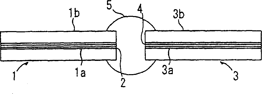
[0111] A V-groove substrate of synthetic silica as shown in Fig. 2 (groove depth: 20 mm; groove angle: 60°) was produced. A single-mode glass optical fiber (core diameter: 50.0 μm) with an outer diameter of 125 μm (core diameter...
Embodiment 2
[0138] 1) Preparation of resin composition
[0139] Put 16.0g (0.05mol) 2,2'-bis(trifluoromethyl)-4,4'-diaminobiphenyl and 152.8g N,N-dimethylacetamide into a 500ml separable flask, The solution was prepared under a nitrogen atmosphere. While stirring, 22.2 g (0.05 mol) of 2,2-bis(3,4-dicarboxyphenyl)hexafluoropropane dianhydride was added to the solution, and the mixture was stirred at room temperature for 24 hours to prepare a polyamic acid solution .
[0140] The polyamic acid solution was diluted with N,N-dimethylacetamide to a solid content of 10%. The pyridine and acetic anhydride of 1.2 times the same amount as the carboxylic acid of the polyamic acid were added to the diluted solution to chemically imidize the polyamic acid. The precipitated polyimide was washed successively with a large amount of water and isopropanol, collected by filtration, and dried at 65° C. under reduced pressure to obtain a white sheet-like polyimide.
[0141] The obtained polyimide was dissolved...
Embodiment 3
[0155] In the same manner as in Example 1, two multimode glass optical fibers were optically connected. The optical loss measured in the same manner as in Example 1 is as follows.
[0156] Distance between glass fibers Connection loss
[0157] 100μm 0.3dB
[0158] 500μm 0.5dB
[0159] 1000μm 1.1dB
[0160] 1500μm 1.7dB
PUM
 Abstract
Description
Claims
Application Information
 - R&D
- Intellectual Property
- Life Sciences
- Materials
- Tech Scout
- Unparalleled Data Quality
- Higher Quality Content
- 60% Fewer Hallucinations
Browse by: Latest US Patents, China's latest patents, Technical Efficacy Thesaurus, Application Domain, Technology Topic, Popular Technical Reports.
© 2025 PatSnap. All rights reserved.Legal|Privacy policy|Modern Slavery Act Transparency Statement|Sitemap|About US| Contact US: help@patsnap.com


