Integral winding stator coil assembly of rotating machine

A technology of stator coils and concentrated windings, applied in windings, electric components, manufacturing motor generators, etc., can solve problems such as difficulties, and achieve the effect of easy fixing and suppressing the increase of losses

Inactive Publication Date: 2004-08-04
DENSO CORP
View PDF3 Cites 14 Cited by
  • Summary
  • Abstract
  • Description
  • Claims
  • Application Information

AI Technical Summary

Problems solved by technology

[0011] Although the above explanation has been made in the case of the tooth coils being connected in series with each other phase by phase, the above-mentioned difficulty also applies to the stator coil group in which the tooth coils are connected in parallel with each other using cross bus bars.

Method used


Image

  • Integral winding stator coil assembly of rotating machine
  • Integral winding stator coil assembly of rotating machine
  • Integral winding stator coil assembly of rotating machine

Examples


no. 1 example

[0036] A first embodiment of a concentrated winding type stator coil assembly according to the present invention included in a rotating electrical machine will now be described with reference to FIGS. 1 to 7 .

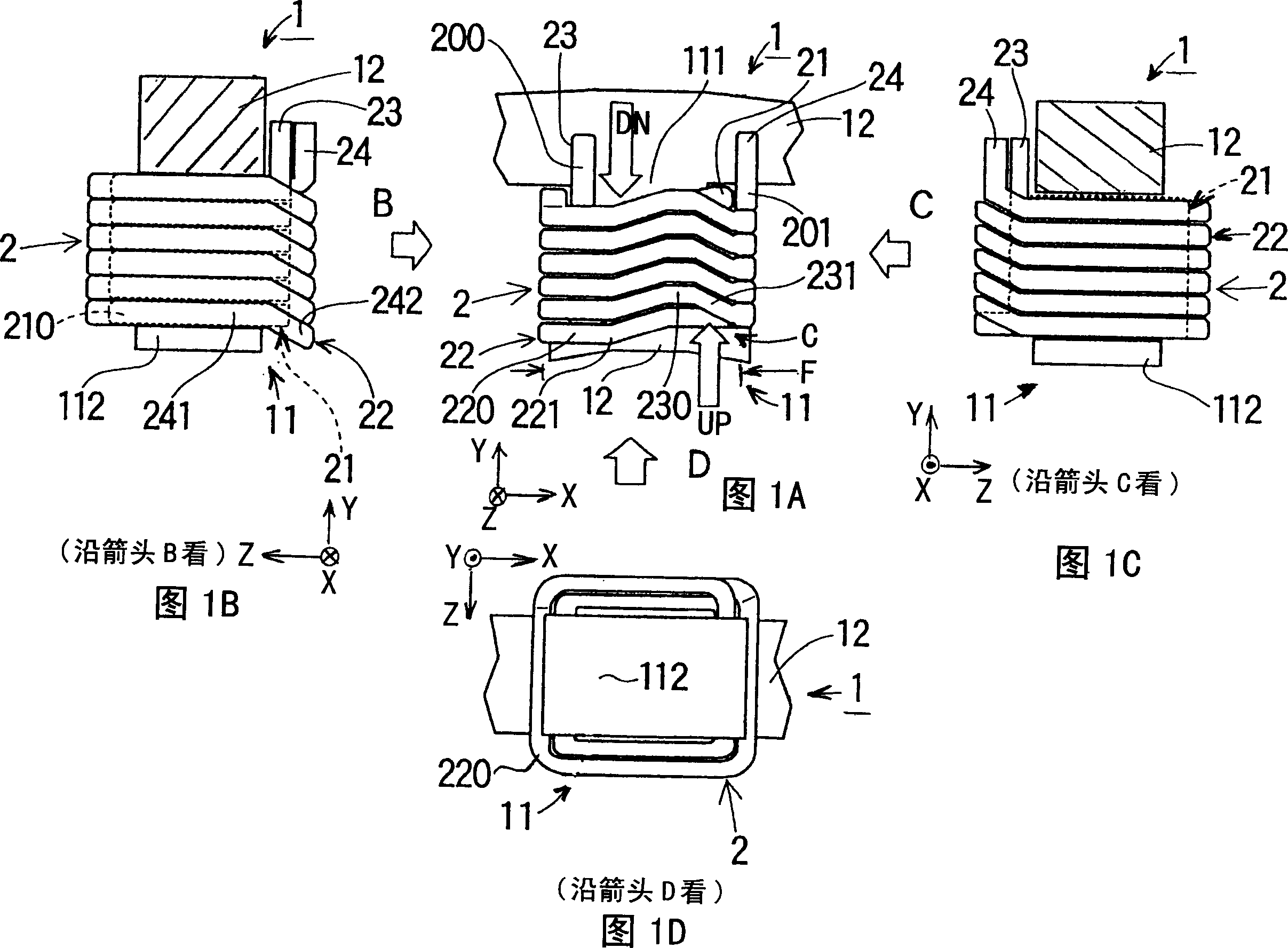
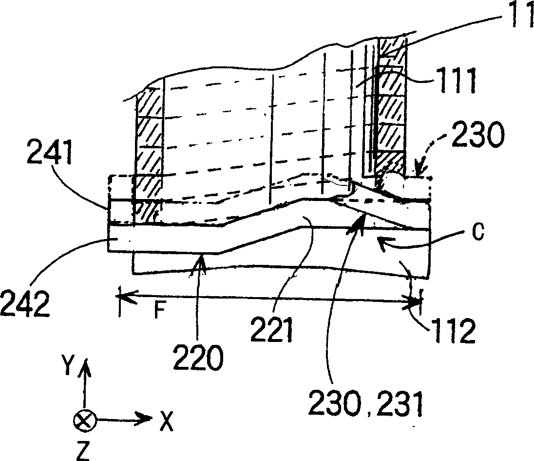
[0037] 1A to 1D are partially shown from various directions equipped with a stator core 1 and teeth 11 formed protruding from the stator core 1 (only one tooth 11 is shown). A coil 2 is wound around each tooth 11 to form a tooth-wound coil called a "tooth coil". In these figures, FIG. 1A shows the coil group seen in the axial direction of the stator core 1, and FIGS. 1B and 1C show the sides of the coil group seen in the directions indicated by arrows B and C, respectively. view, and FIG. 1D is a bottom view of the coil set seen along the direction indicated by arrow D.

[0038] In FIGS. 1A to 1D , three orthogonal directions are defined so that, as shown in FIG. 1A , the axial direction of the stator core 1 (hereinafter referred to as "core axial direction") correspo...

no. 2 example

[0082] will now refer to Figure 8 , describes a concentrated winding type stator coil assembly according to a second embodiment of the present invention.

[0083] Specifically, the second embodiment describes a phase winding configured by connecting tooth coils in parallel with each other.

[0084] In the second and subsequent embodiments, the same reference numerals are given to the same or similar components in structure and / or function as in the description of the foregoing first embodiment, and detailed descriptions thereof are omitted.

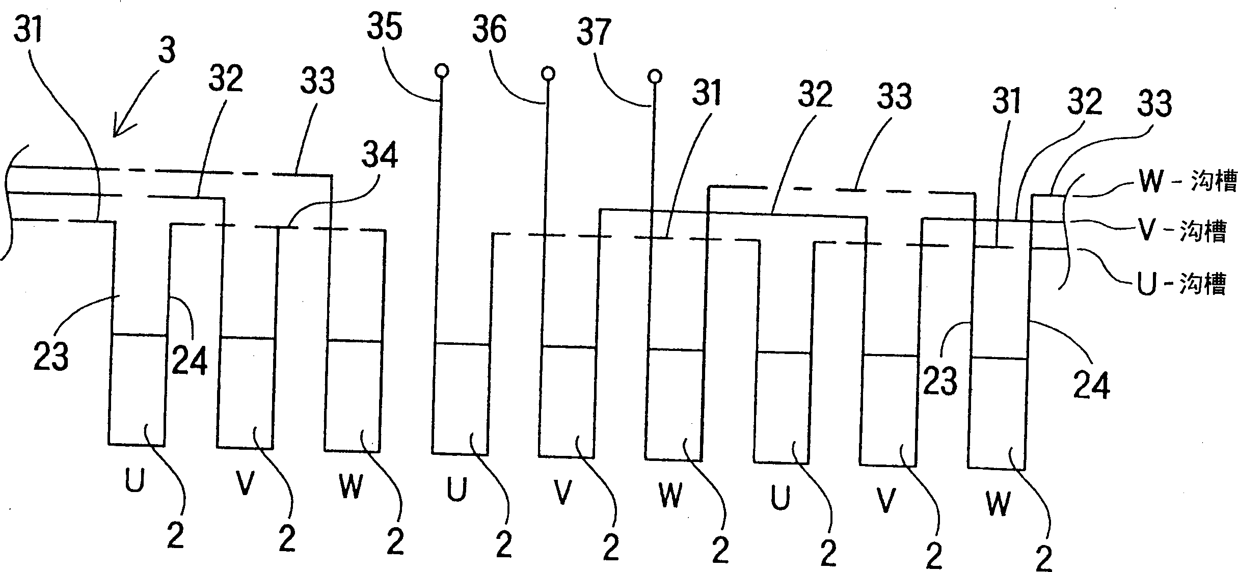
[0085] In this example, if Figure 8 As shown, four ring bus bars 300 to 304 are used to form a three-phase star connection. These bus bars are composed of a W-phase bus bar 300 , a V-phase bus bar 301 , a U-phase bus bar 302 , and a neutral point bus bar 303 . Incidentally, the remaining components of the stator coil assembly according to the second embodiment are similar or identical to those of the first embodiment.

[0086]Althou...

no. 3 example

[0088] A concentrated winding type stator coil assembly according to a third embodiment of the present invention will now be described with reference to FIGS. 10A to 10D.

[0089] The stator coil group according to this embodiment is structurally similar or identical to the stator coil group described in the first and second embodiments, except that the tooth coil 2 is wound in another way. Specifically, in the present embodiment, the tooth coil 2 is produced so as to have the second layer type coil 22 in which only the lower bent portion is formed (refer to arrow DN in FIG. 10A).

[0090] As with the stator coil group shown in FIGS. 1A to 1D , FIGS. 10A to 10D are partially shown from various directions equipped with a stator core 1 and teeth 11 formed protruding from the stator core 1 (only one tooth is shown). 11) The stator core unit. The coil 2 is wound around each tooth 11 to form a tooth wound coil (tooth coil). In these drawings, FIG. 10A shows a coil group seen in t...


PUM


Abstract

A concentrated-winding type stator coil unit for a rotary electric machine is provided with a stator core having a core back and teeth protruding from the core back. Plural coils are wound around the teeth respectively. Each coil is composed of, for example, a first layered coil formed by winding a coil wire in a layer around each tooth to form plural turns arranged in parallel on each tooth and a second layered coil formed by winding the coil wire in a layer to from plural turns around the first layered coil wound around each tooth. The last turn of the first layered coil continues to the first turn of the second layered coil. Both ends of the coil wire are located at and on a base potion of each of the teeth as a winding-start end and a winding-finish end of each of the coils.

Description

technical field [0001] BACKGROUND OF THE INVENTION Field of the Invention The present invention relates to a stator coil assembly of a rotating electrical machine such as a motor and a generator, and more particularly, to a concentrated winding type stator coil assembly of a rotating electrical machine. Background technique [0002] In a rotating electrical machine, a stator is required to convert electrical energy into kinetic energy and vice versa. Currently, various types of stators exist. [0003] One type of stator has coils each wound in a concentrated manner around each tooth (serving as a magnetic pole) of the stator core, the wound coils (often referred to as tooth coils) being connected to each other phase by phase to form each phase coil. Such a stator is called a "concentrated winding stator". When winding a coil around each tooth to manufacture a concentrated winding type stator, an assembled type core in which partial cores separated tooth by tooth are assem...

Claims


Application Information

Patent Timeline
Patent Type & Authority Applications(China)
IPC IPC(8): H02K3/04H02K3/18H02K3/52H02K15/095
CPCH02K15/095H02K3/522H02K3/18Y10T29/49071
Inventor 米田繁则濑口正弘猪俣宪安
Owner DENSO CORP
Why Eureka
Try Eureka