Equipment and method for generating directional sound wave

A directivity and sound wave technology, applied in the field of ultrasonic technology, can solve problems such as difficult sound enclosed spaces

Inactive Publication Date: 2004-08-11
FORTEMEDIA
View PDF0 Cites 10 Cited by
  • Summary
  • Abstract
  • Description
  • Claims
  • Application Information

AI Technical Summary

Problems solved by technology

However, due to the above reasons, conventional designs have difficulty forming such small sound enclosures

Method used


Image

  • Equipment and method for generating directional sound wave
  • Equipment and method for generating directional sound wave
  • Equipment and method for generating directional sound wave

Examples


Embodiment Construction

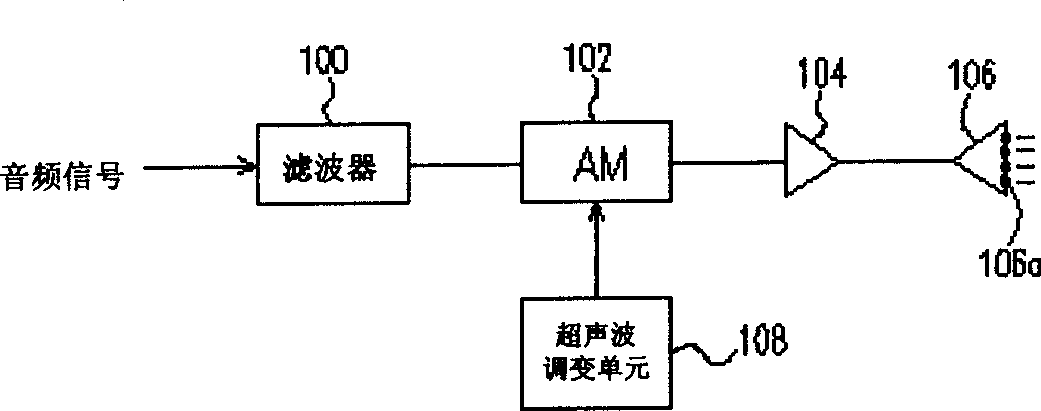
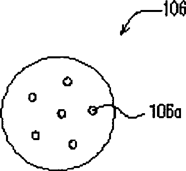
[0024] One of the main features of the present invention is to perform a pre-compensation on an audio signal before performing the amplitude modulation action and loading an ultrasonic carrier wave on the audio modulation, which is based on an ultrasonic air self-demodulation mechanism designed and selected to perform a pre-compensated. Therefore, when the ultrasonic wave is self-demodulated in the air, the audio signal can be demodulated more easily. In this way, the array design of the ultrasonic generating units is reduced, thereby allowing the design of a non-array structure using a single unit. Can at least achieve the design of a small sound enclosed space.

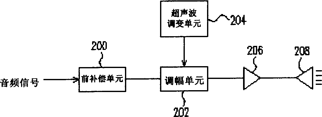
[0025] According to the design principle of the present invention, image 3 In accordance with the present invention, a block diagram of an apparatus for generating directional sound waves. At image 3 Among them, a device for generating directional sound waves of the present invention includes a pre-compensatio...


PUM


Abstract

An equipment for generating directional sound waves is composed of a pre-compensating unit to receive an audio signal for pre-compensating and output a signal, an ultrasonic modulation unit for providing an ultrasonic carrier, an AM unit for receiving said output signal to modulate said carrier, a power amplifier, and a directional ultrasonic wave beam emitting element. Said carrier is locally demodulated by air itself to be reduced to audio signals, which can be heared only in the local region.

Description

technical field [0001] The present invention relates to an ultrasonic technology. In particular, it relates to a device and method for generating directional sound waves, which has the function of directional sound generation and can be applied in the range of short-distance and small spaces. Background technique [0002] Ultrasound has been widely used in daily life. Its application level can range from medical applications, detectors, to applications in dead ends of daily laundry items. However, since the frequency bandwidth of the ultrasonic wave is outside the audio frequency range of the human ear, the ultrasonic wave will not directly affect the human hearing effect. However, after further research on the physical effects of ultrasonic waves in air media, ultrasonic waves have some characteristics that can be utilized. [0003] One of the important characteristics of ultrasonic waves is that it has strong directivity when propagating in the air. That's why bats use...

Claims


Application Information

Patent Timeline
Patent Type & Authority Applications(China)
IPC IPC(8): B06B3/00
Inventor 李晓东
Owner FORTEMEDIA
Why Eureka
Try Eureka