Supercharge Your Innovation With Domain-Expert AI Agents!

Switch gear

A technology for switchgear and housings, applied in the direction of electric switches, electric heating devices, electrical components, etc., can solve problems such as maintenance and management difficulties, increased sealing procedures, and increased costs

Inactive Publication Date: 2004-08-18
ALPS ALPINE CO LTD
View PDF1 Cites 4 Cited by
  • Summary
  • Abstract
  • Description
  • Claims
  • Application Information

AI Technical Summary

Problems solved by technology

[0005] However, in the sealing structure of the above-mentioned conventional switchgear, no matter in the case of welding the bonding surface, or in the case of flowing an adhesive into the gap between the fitting surfaces for bonding, since the assembly of the switchgear is completed, Since processes such as welding and bonding are performed, there is a problem of increasing the cost of the sealing process and increasing the cost. In addition, special equipment for sealing is required, so there is a problem of difficult maintenance and management

Method used


Image

  • Switch gear
  • Switch gear
  • Switch gear

Examples


Embodiment Construction

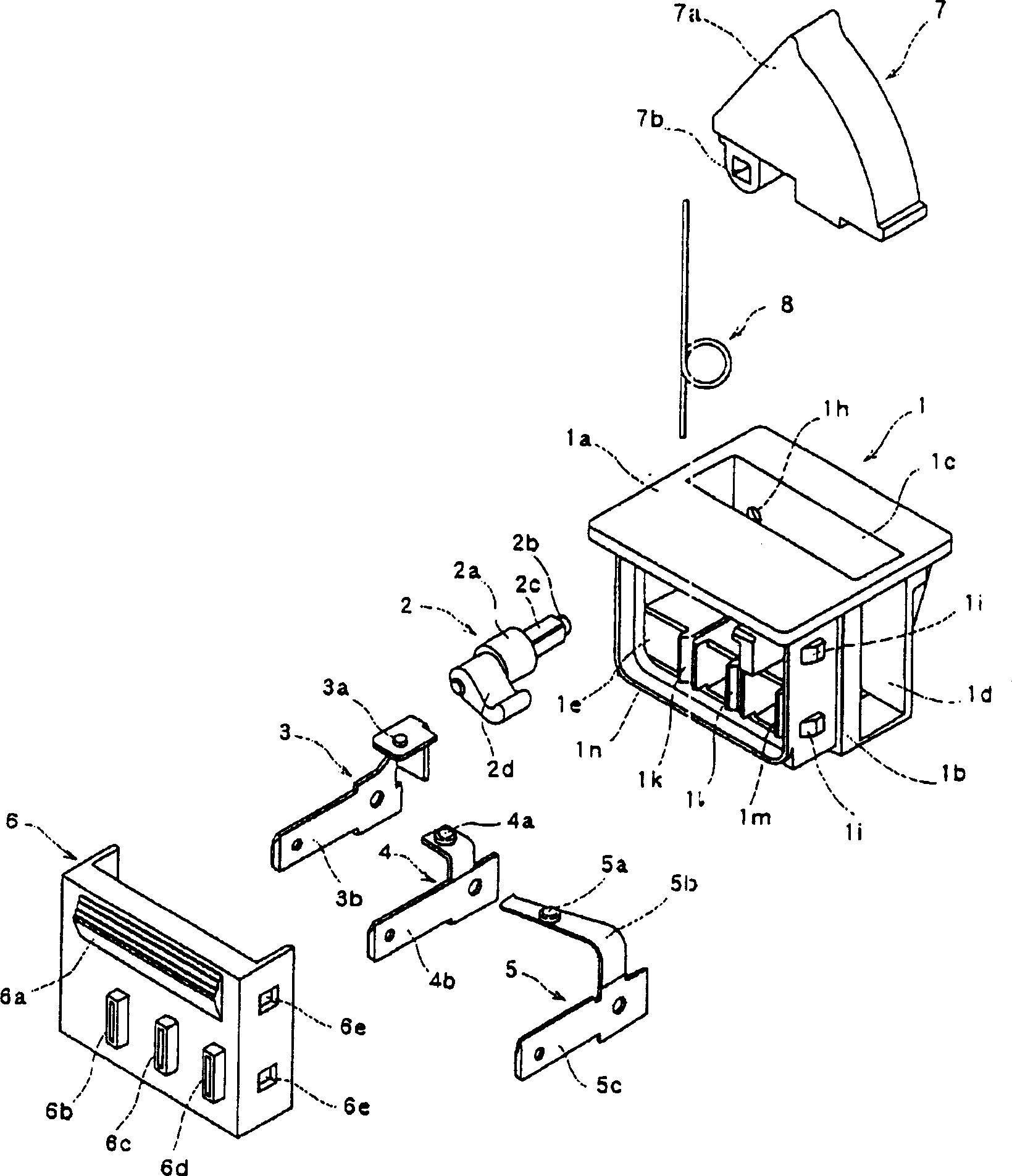
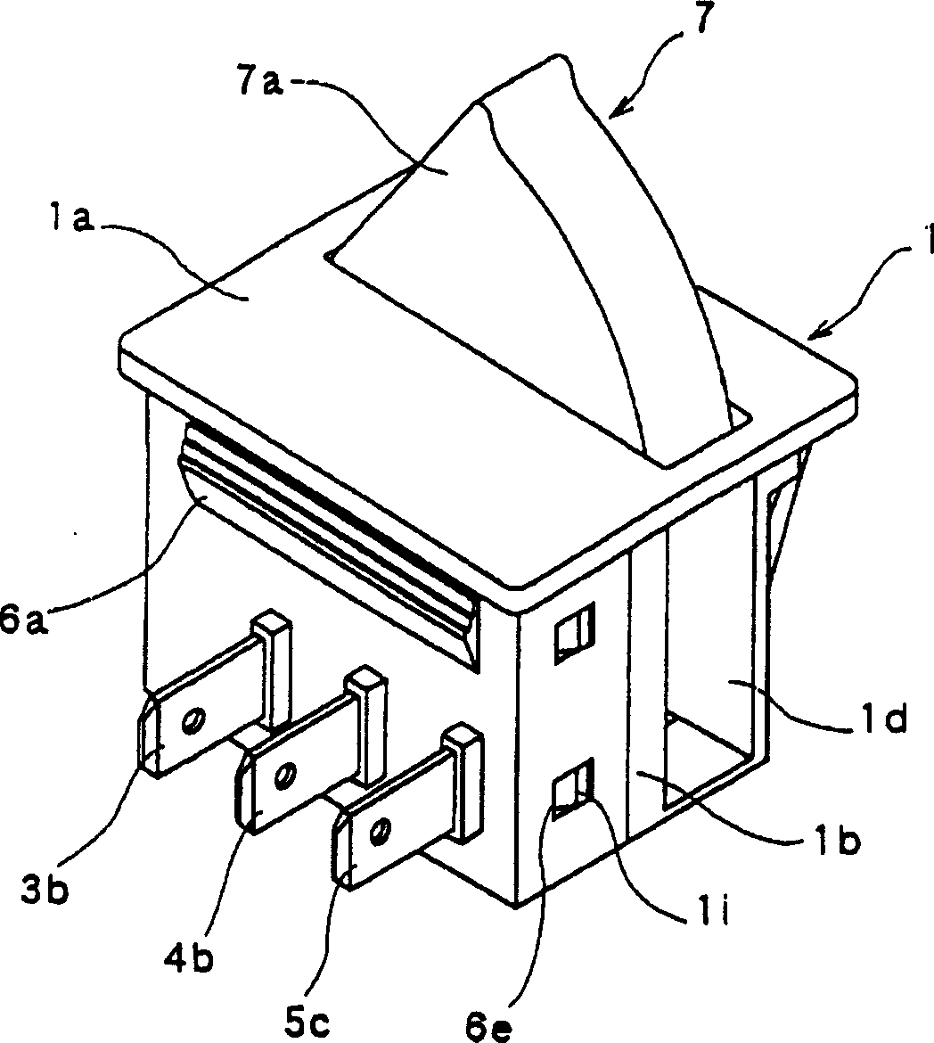
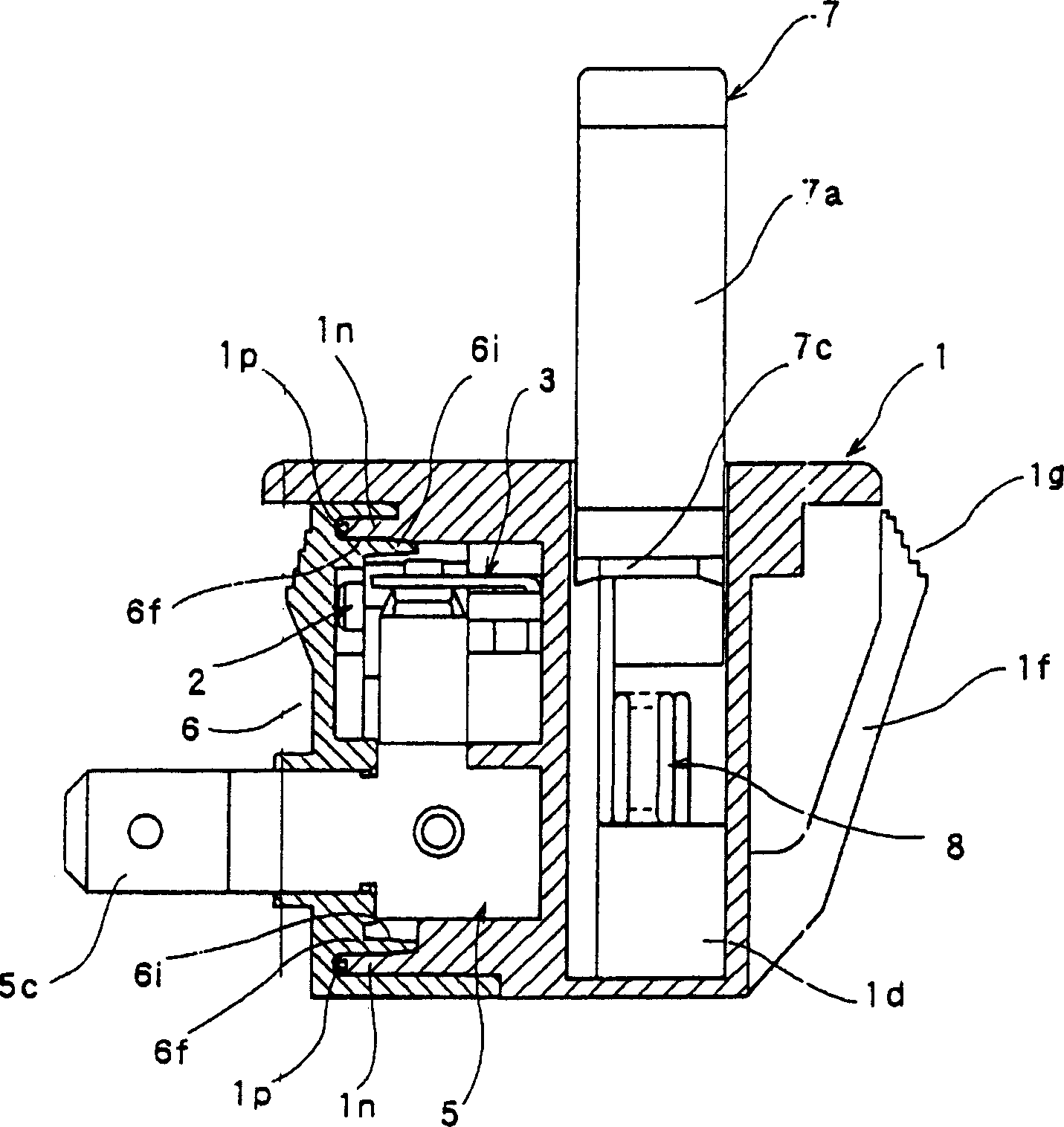
[0018] Below, the embodiment of the present invention is such as Figure 1 to Figure 6 shown. figure 1 is an exploded oblique view of the switchgear, figure 2 is the overall oblique view of the switchgear, image 3 is a cross-sectional view of the switchgear, Figure 4 It is a partial sectional view showing the fitting state of the case and the cover, Figure 5 It is a front view of the contact part showing the initial state, Image 6 It is a front view of the contact part showing the operating state.

[0019] In the figure, the casing 1 is formed in a roughly square shape from an insulating material such as synthetic resin, and is composed of a flat panel portion 1a and a base portion 1b connected to the panel portion 1a. A window portion 1c is formed on the upper surface of the panel portion 1a, and a lever 7 described later is rotatably inserted into the window portion 1c. Furthermore, an opening 1 d is provided which is continuous with the window 1 c and opens on on...


PUM


Abstract

Provided is a switch-gear shield structure that requires no special post-process such as welding and bonding to achieve low cost and high sealing performance with a simple structure in which two components are merely fitted together. A ring-shaped projected wall (1n) is formed at one side of the joint of a casing (1) and a cover (6), while a ring-shaped recessed groove (6f) to be fitted to the projected wall (1n) is formed on the other side, wherein the ring-shaped projected wall (1n) has an elastic transformable part (1p) at the end and the ring-shaped recessed groove (6f) has an inclined part (6g) forming a slope in the vicinity of the bottom; thus, the casing (1) and the cover (6) are tightly fitted together by the pressure contact of the elastic transformable part (1p) with the inclined part (6g).

Description

technical field [0001] The present invention relates to a switchgear, and particularly relates to a sealing structure of a switchgear used in a refrigerator or the like. Background technique [0002] In conventional sealing structures of switchgears, for example, when fitting the case and the cover, heating the case and the cover after overlapping them, or welding and sealing the joint surface by ultrasonic waves or the like is known. [0003] In addition, it is also known that after the casing and the cover are superimposed, a resin adhesive is flowed into the gap between the mutual fitting surfaces to bond, thereby sealing (for example, refer to Patent Document 1 and Patent Document 1). 2). [0004] [Patent Document 1]: Japanese Patent Application Publication No. 07-006660; [Patent Document 2]: Japanese Patent Application Publication No. 13-077503. [0005] However, in the sealing structure of the above-mentioned conventional switchgear, no matter in the case of welding ...

Claims


Application Information

Patent Timeline
Patent Type & Authority Applications(China)
IPC IPC(8): H01H13/04H01H9/04H01H13/06H01H21/08H01H21/24
CPCH01H21/24H01H2011/062H01H9/04H05B3/03H05B3/20
Inventor 武田昌之
Owner ALPS ALPINE CO LTD
Features
  • R&D
  • Intellectual Property
  • Life Sciences
  • Materials
  • Tech Scout
  • Unparalleled Data Quality
  • Higher Quality Content
  • 60% Fewer Hallucinations
Learn More