Cathode ray tube having an improved electron gun

A cathode ray tube and electron gun technology, applied in the direction of cathode ray tube/electron beam tube, discharge tube, circuit, etc.

Inactive Publication Date: 2004-08-18
MERIDIAN SOLAR & DISPLAY
View PDF0 Cites 0 Cited by
  • Summary
  • Abstract
  • Description
  • Claims
  • Application Information

AI Technical Summary

Problems solved by technology

[0049] In such a case, the focused electron beam becomes asymmetrical on both sides, and one si

Method used


Image

  • Cathode ray tube having an improved electron gun
  • Cathode ray tube having an improved electron gun
  • Cathode ray tube having an improved electron gun

Examples


Embodiment Construction

[0077] With reference to the drawings, the following detailed description will introduce a cathode ray tube according to a preferred embodiment of the present invention.

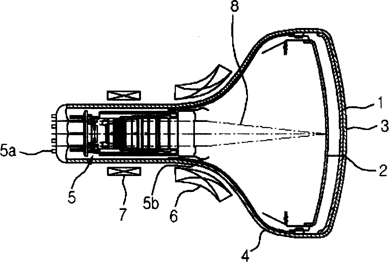
[0078] The cathode ray tube of the present invention includes: a panel with a phosphor screen formed on the inner surface, a funnel-shaped device connected to the panel, an electron gun that emits electrons, a deflection yoke, the deflection yoke for deflection in the horizontal and vertical directions Electron beam, and a shadow mask with electron beam color selection function.

[0079]Preferably, the outer surface of the panel is substantially flat, and the inner surface has a specified curvature. In addition, the funnel-shaped device has a coil mounting part on which a deflection yoke is mounted, and the shape of the coil mounting part gradually changes from a circular shape to a non-circular shape in the direction from the neck side to the panel side.

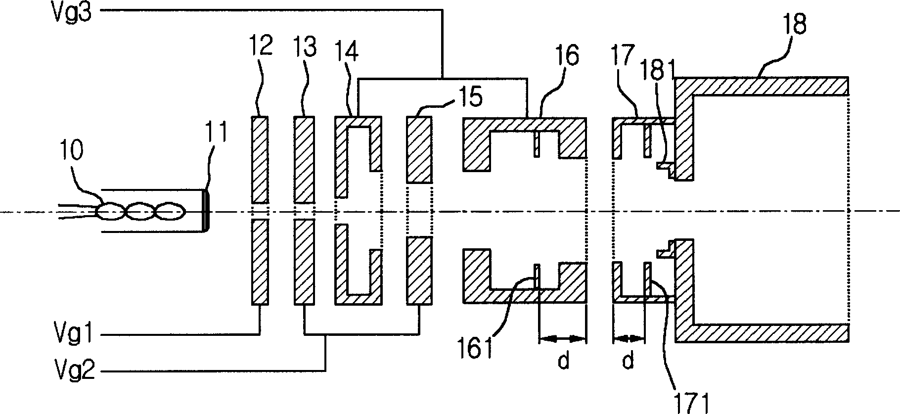
[0080] In this type of cathode ray tube, the electrodes...


PUM

PropertyMeasurementUnit
Depthaaaaaaaaaa

Abstract

A cathode ray tube has a low focus degradation, optimum focus characteristic and improved resolution by optimizing a relation between a horizontal inside diameter of a rim portion, which is a common opening portion of main lens forming electrodes for focusing electron beams onto a screen, and a horizontal distance between outside end of one outer electron beam passing hole to outside end of the other outer electron beam passing hole of a correction electrode.

Description

Technical field [0001] The present invention relates to a cathode ray tube, and in particular to a cathode ray tube with low focus degradation, optimized focusing characteristics and improved resolution. This is achieved by optimizing the horizontal inner diameter at the edge portion and the correction electrode. The relationship between the outer end of the outer electron beam through hole and the outer end of the other outer electron beam through hole is realized, and the edge portion is a common opening portion constituting the main lens of the electrode for focusing the electron beam on the screen. Background technique [0002] figure 1 A related art cathode ray tube is explained. [0003] As shown in the figure, a cathode ray tube usually includes: a phosphor screen 1 coated with R, G, and B phosphors on the inner surface, a panel 3 connected to a shadow mask 2 with a color selection function, and a panel connected to the panel 3 connected funnel-shaped device 4, so togeth...

Claims


Application Information

Patent Timeline
IPC IPC(8): H01J29/48H01J29/50
CPCH01J29/503H01J29/48
Inventor 金闰镇李宰豪
Owner MERIDIAN SOLAR & DISPLAY
Why Eureka
Try Eureka