Control device of yarn twisting machine

A control device and a technology for a twisting machine, which are used in spinning machines, continuously wound spinning machines, textiles and papermaking, etc., and can solve the problems of poor twist count accuracy and increased influence of twist counts.

Inactive Publication Date: 2004-08-25
MURATA MASCH LTD
View PDF0 Cites 4 Cited by
  • Summary
  • Abstract
  • Description
  • Claims
  • Application Information

AI Technical Summary

Problems solved by technology

[0016] On the other hand, in a single-spindle drive type twister that needs to decelerate and stop the spindle shaft and drum in a short time, since the winding amount of the yarn from the start of deceleration to the stop is small, the winding caused by the lag angle The influence of the change of the yarn length on the number of twists increases, and there is a problem that the accuracy of the number of twists of the twisted yarn deteriorates

Method used


Image

  • Control device of yarn twisting machine
  • Control device of yarn twisting machine
  • Control device of yarn twisting machine

Examples


Embodiment Construction

[0038] Embodiments of the present invention will be described below using the drawings.

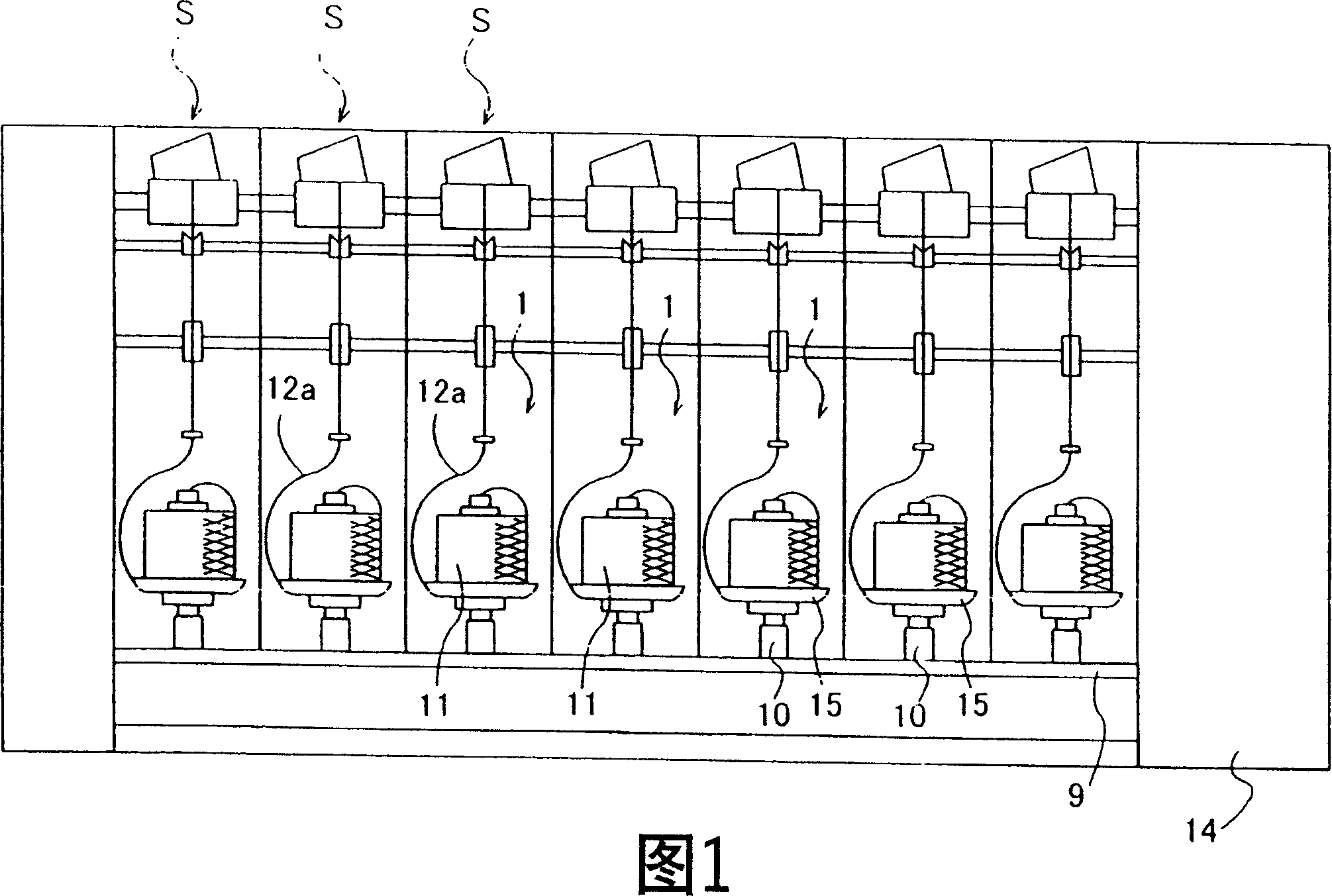
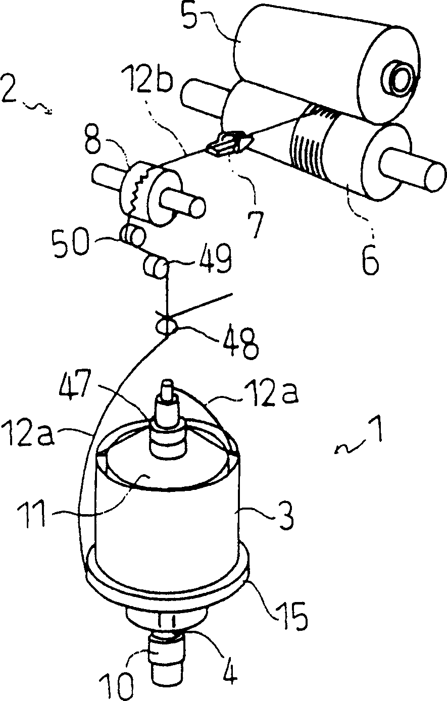
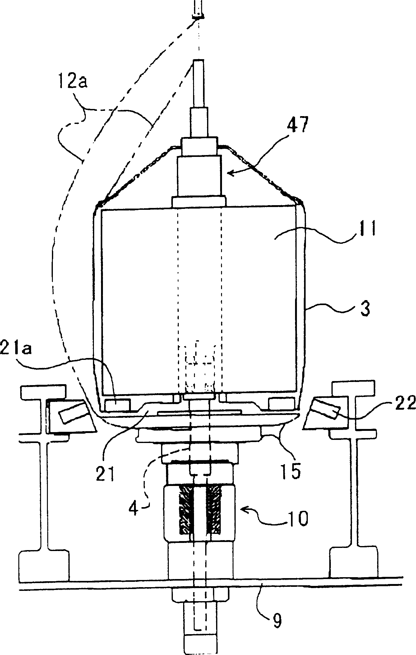
[0039] Fig. 1 is the whole front view that shows the single-spindle drive type twisting machine equipped with the control device of the present invention, figure 2 It is a perspective view showing the structure of one spindle of a single spindle drive type twister, image 3 It is a partial cross-sectional view showing the spindle device of the single-spindle-driven twister when viewed from the front, Figure 4 It is a block diagram showing the control device of the single spindle drive type twister, Figure 5 It is a graph showing the degree of deceleration and stop of the spindle drive motor and drum drive motor during deceleration and stop control. Figure 6 It is a perspective view showing a memory disc in a state where the hysteresis angle is large, Figure 7 It is a perspective view showing the storage disc in a state where the hysteresis angle is small.

[0040] Next, an embodim...


PUM


Abstract

The controlling device of the yarn twister is provided with a spindle apparatus 1, a spindle-driving motor 10, a spindle changer, a winding motor, a slowdown and stop controlling means 74 for the spindle driving motor, and a slowdown and stop controlling means 73 for a drum driving motor. The delay angle of the spindle apparatus 1 is included in the parameters for setting the slowdown and stop rate of the spindle driving motor 10 or the drum driving motor 20 controlled by the slowdown and stop controlling means 74 for the spindle driving motor or the slowdown and stop controlling means 73 for the drum driving motor.

Description

technical field [0001] The present invention relates to a control device for a twisting (yarn) machine, and more particularly to a technique for controlling the degree of deceleration and stop of a spindle (spindle) driving motor or a winding motor. Background technique [0002] In the prior art, twisters are known for twisting yarns unwound from yarn feed packages. Most of them are simultaneous drive type twisters configured by winding one drive belt around each of a plurality of parallel spindle shafts, and simultaneously driving a plurality of spindle shafts with one drive motor using the drive belt. In such a twisting machine, the drive of the drum of the winding device for winding the yarn unwound from the yarn feeding package is transmitted from the spindle shaft driving motor through the transmission device. [0003] On the other hand, in recent years, in order to reduce the noise and power loss when driving, drive motors are respectively provided on each spindle dev...

Claims


Application Information

Patent Timeline
Patent Type & Authority Applications(China)
IPC IPC(8): D01H1/36D01H1/244D01H7/22D01H13/14
Inventor 梅冈利成
Owner MURATA MASCH LTD
Why Eureka
Try Eureka