
A design method for antenna impedance matching circuit

A technology of impedance matching circuit and matching circuit, applied in the direction of antenna, impedance network, electrical components, etc., can solve the problem of increasing design cost

Inactive Publication Date: 2004-08-25
BENQ CORP
View PDF0 Cites 11 Cited by
  • Summary
  • Abstract
  • Description
  • Claims
  • Application Information

AI Technical Summary

Problems solved by technology

[0003] However, in some cases, changes to the antenna impedance matching circuit will delay the design process or increase the design cost

Method used


Image

  • A design method for antenna impedance matching circuit
  • A design method for antenna impedance matching circuit
  • A design method for antenna impedance matching circuit

Examples


Embodiment Construction

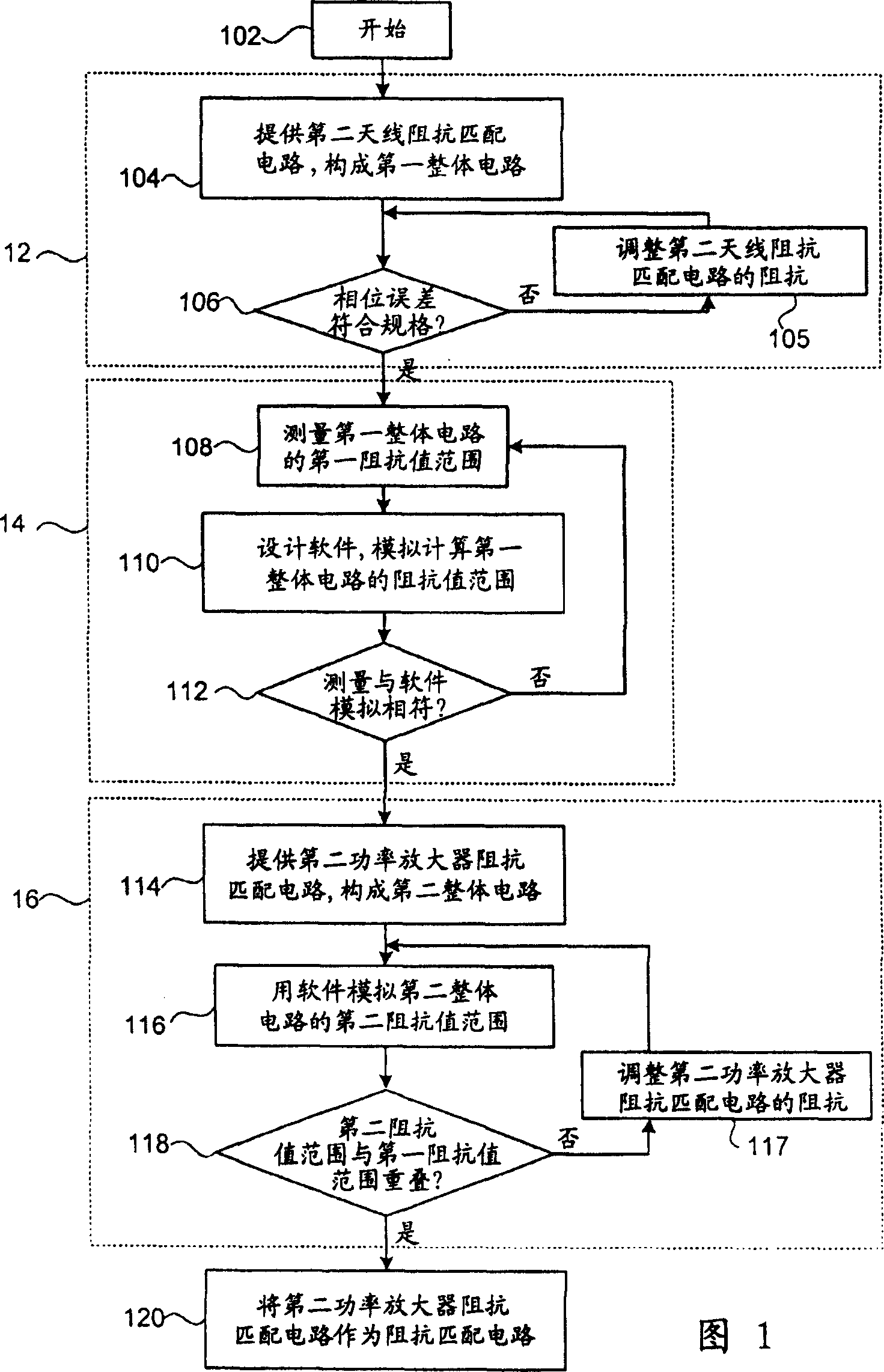
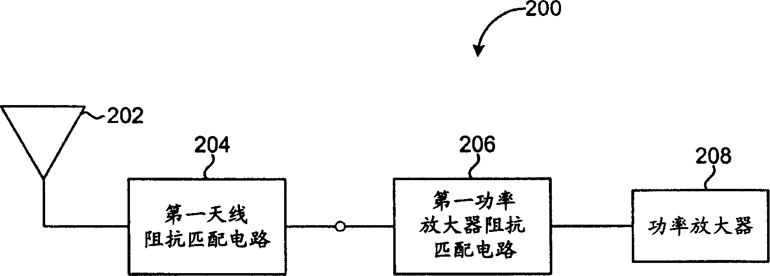
[0032] The present invention provides a method for designing an impedance matching circuit, and the flow chart of its preferred embodiment is shown in FIG. 1 . figure 2 It is the overall circuit 200 of the original design. Under the condition of keeping the first antenna impedance matching circuit 204 unchanged, the method of the present invention changes the first power amplifier impedance matching circuit 206 so that the phase error of the changed whole circuit 200 meets the predetermined specification.

[0033] Referring to Fig. 1, the steps of this preferred embodiment can be divided into three major stages. In the first stage 12, the impedance matching circuit of the antenna is changed first, but the impedance matching circuit of the power amplifier is not changed, so that the phase error of the whole circuit meets the predetermined specification. The second stage 14 estimates the trajectory of the impedance value of the overall circuit in the Smith chart. The third sta...


PUM


Abstract

This invention provides a method for designing antenna impedance match circuit used in matching power amplifier and an antenna circuit initially including an antenna and a first antenna impedance match circuit. A second circuit is provided to be matched with that of the first power amplifier to constitute an integral circuit which impedance forms a first trace on the smith chart and its phase error is regulated. In addition, a second power amplifier impedance match circuit is designed to be matched with the first antenna circuit to make up of another integral circuit and the impedance forms a second trace on the smith chart and the system gets the phase error in conformity with the predesigned specifications when the two overlapped.

Description

technical field [0001] The invention relates to a method for designing an impedance matching circuit, in particular to a method for matching a power amplifier and an antenna circuit into a circuit whose phase error meets specifications. Background technique [0002] When designing a wireless receiving / transmitting circuit of a wireless communication device, it is necessary to design an antenna impedance matching circuit for matching antenna impedance and a power amplifier impedance matching circuit for adjusting power amplifier impedance. Generally, when adjusting the matching of the antenna circuit, because the power amplifier and other circuits at the back end of the impedance matching circuit of the power amplifier are more complicated, there are many problems involved, so in the design, the impedance matching circuit of the power amplifier will not be changed when adjusting the impedance. , but by means of the adjustment of the antenna impedance matching circuit to achie...

Claims


Application Information

Patent Timeline
IPC IPC(8): H01Q3/00H03H7/38H04B1/18H04B1/40
Inventor 陈俊仁吴柏府苏家宏
Owner BENQ CORP
Learn More