Impedance matching circuit design method

a technology of impedance matching and design method, which is applied in the direction of impedence matching network, instrumentation, program control, etc., can solve the problems of phase error meeting specification and phase error meeting phase error

Inactive Publication Date: 2006-08-29
BENQ CORP
View PDF2 Cites 5 Cited by
  • Summary
  • Abstract
  • Description
  • Claims
  • Application Information

AI Technical Summary

Problems solved by technology

The method, instead of altering the antenna impedance matching circuit, designs an impedance matching circuit, which makes the phase error meet the specification by comparing impedance range.
Then the second overall circuit also has phase error meeting the specification.

Method used


Image

  • Impedance matching circuit design method
  • Impedance matching circuit design method
  • Impedance matching circuit design method

Examples


Embodiment Construction

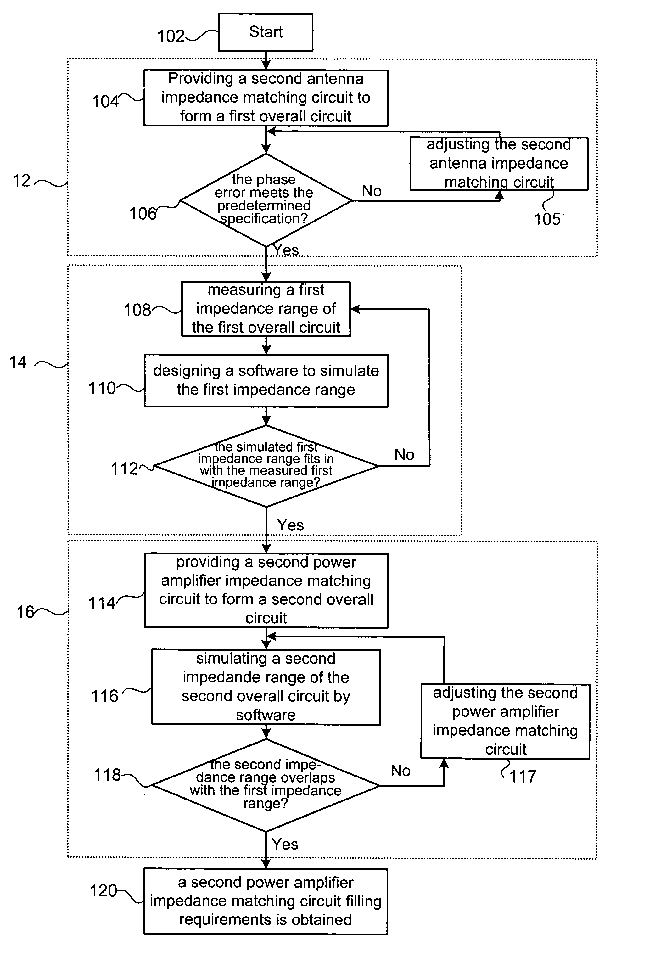
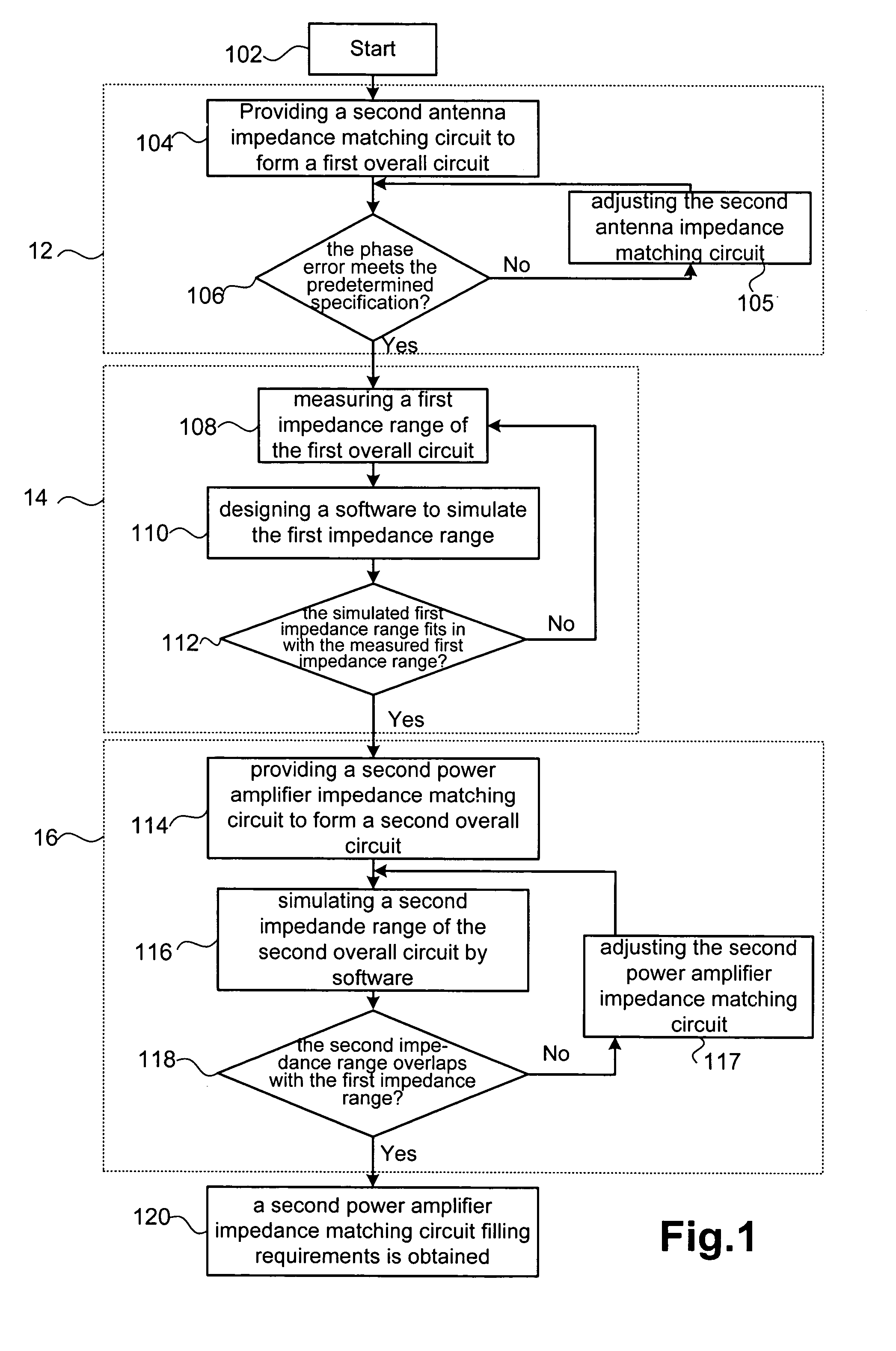
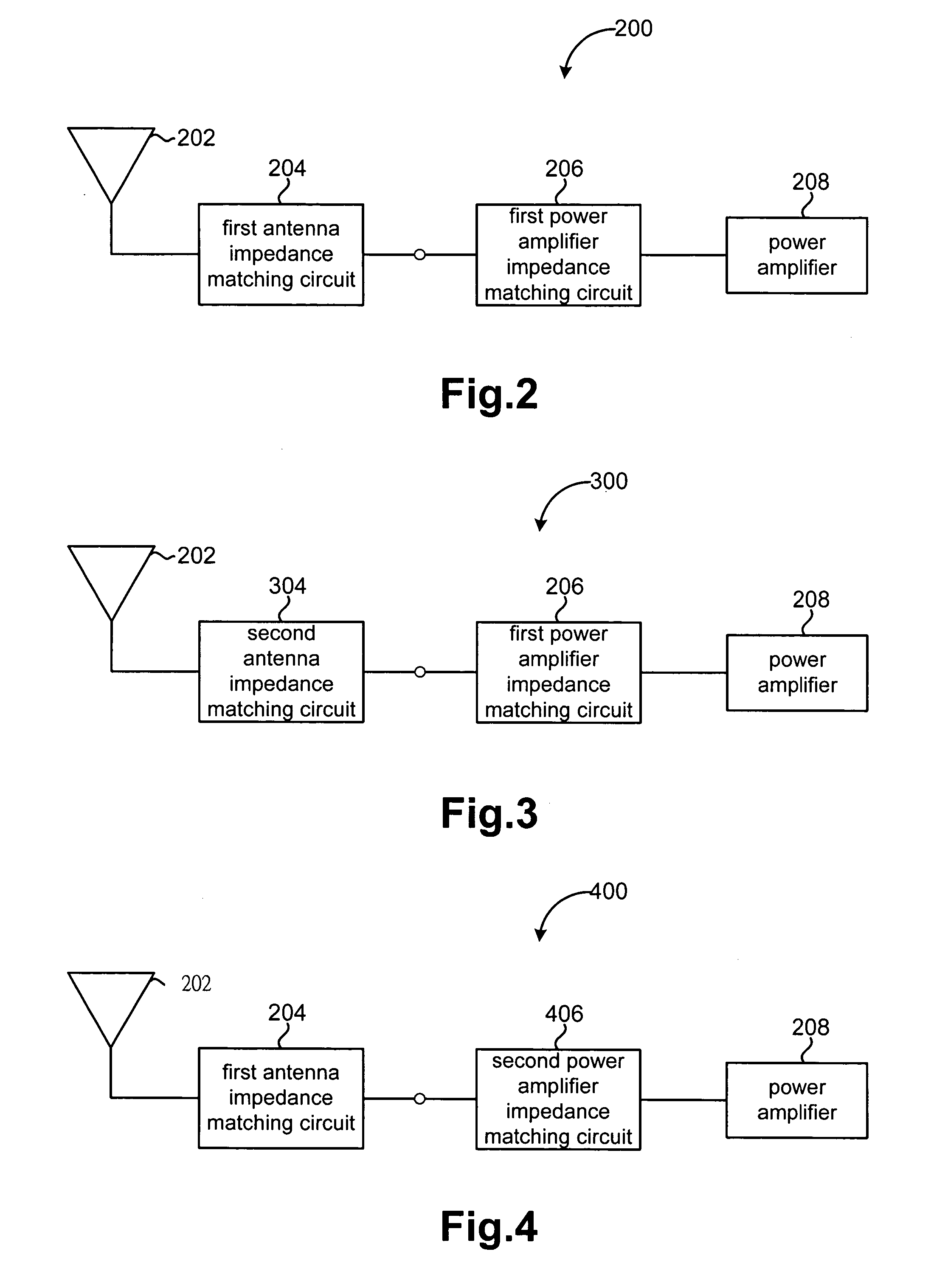
[0018]A method for designing an impedance matching circuit is provided. FIG. 1 is a flow chart of a preferred exemplary embodiment. FIG. 2 is a block diagram of an original overall circuit 200. On condition that the first antenna impedance matching circuit 204 is kept, the first power amplifier impedance matching circuit 206 is modified to make the phase error of the overall circuit 200 meet a predetermined specification.

[0019]Referring to FIG. 1, the preferred exemplary embodiment has three stages. In the first stage 12, the antenna impedance matching circuit is altered to make the phase error of the overall circuit, with the same power amplifier impedance matching circuit, meet a predetermined specification. In the second stage 14, the impedance range of the overall circuit is estimated, and displayed by a locus on the Smith Chart. In the third stage 16, a new power amplifier impedance matching circuit is used for matching the original antenna impedance matching circuit to form an...


PUM


Abstract

The present invention provides a method for designing an impedance matching circuit. The impedance matching circuit is for matching a power amplifier and an antenna circuit. The antenna circuit originally includes an antenna and a first antenna impedance matching circuit. For suiting the design modification of the power amplifier, the method provides a second antenna impedance matching circuit, and matches it with a first power amplifier impedance matching circuit to constitute an overall circuit. The impedance of the overall circuit forms a first locus on the Smith Chart, and is made to have a phase error meeting a predetermined specification. Next, the second power amplifier impedance matching circuit is designed and matched with the first antenna impedance matching circuit to constitute another overall circuit. And the impedance of this overall circuit forms a second locus on the Smith Chart. As the second locus overlaps the first locus, the system has a phase error meeting a predetermined specification.

Description

CROSS-REFERENCE TO RELATED APPLICATIONS[0001]This application claims priority of Taiwan Patent Application Serial No. 091137439 filed on Dec. 26, 2002.FIELD OF INVENTION[0002]The present invention relates to a method for designing an impedance matching circuit, and especially to a method for matching a power amplifier and an antenna impedance matching circuit to form a circuit with phase error meeting a predetermined specification.BACKGROUND OF THE INVENTION[0003]An antenna impedance matching circuit designed for matching an antenna and a power amplifier impedance matching circuit designed for matching a power amplifier are necessary components of receiving / transmitting circuit of wireless communication systems. Modifying the power amplifier impedance matching circuit is a more complicated way of improving overall impedance matching. Therefore, instead, it is typical to modify the antenna impedance matching circuit to meet the requirement.[0004]However, modifying the antenna impedan...

Claims


Application Information

Patent Timeline
Patent Type & Authority Patents(United States)
IPC IPC(8): G06F17/50H01Q1/50H03H11/28
CPCG06F17/5063G06F30/36
Inventor CHEN, CHUN-ZENWU, BO-FUSU, CHIA-HUNG
Owner BENQ CORP
Why Eureka
Try Eureka