Non-reciprocal device

a non-reciprocal, non-reciprocal technology, applied in waveguide devices, basic electric elements, electrical equipment, etc., can solve the problem of serious interference with the attempt to reduce the size or thickness of the non-reciprocal device, and achieve the effect of reducing the insertion loss, broad frequency band, and enabling compaction and thinning

Inactive Publication Date: 2006-06-06
TDK CORPARATION
View PDF10 Cites 5 Cited by
  • Summary
  • Abstract
  • Description
  • Claims
  • Application Information

AI Technical Summary

Benefits of technology

[0010]The object of the present invention is to provide a non-reciprocal device which can reduce the insertion loss, enables compaction and thinning, and can treat a broad frequency band.
[0016]In the non-reciprocal device of the present invention, the intensity of the DC magnetic field, which is applied by the permanent magnet to the gyromagnetic component, is adjusted such that, in a Smith chart where the center represents the normalized impedance, the impedance of the gyromagnetic component is positioned at a value which is on a constant conductance circle smaller than the reference constant conductance circle passing the center and which is on a constant reactance line above the reference constant reactance line passing the center. This allows the permanent magnet to have a lowered magnetic field and resultant reduced thickness, in comparison with a conventional non-reciprocal device in which the magnetic field is adjusted such that the impedance of the gyromagnetic component is positioned at a value on the reference constant conductance circle passing the center.
[0019]Thus, the impedance seen from the input / output terminals of the non-reciprocal device is set at the center of the Smith chart, and impedance matching is achieved, thereby reducing insertion loss.
[0020]Moreover, even if a small, soft ferrite body is employed, it is possible to maintain the impedance of the center conductor at a sufficiently high level, and thus to broaden the operable frequency band.
[0021]Furthermore, the capacitor connected in parallel with the center conductor is allowed to have a reduced capacitance and so, that capacitor is reduced in size. In conclusion, according to the invention, it is possible to reduce the size and thickness of a non-reciprocal device by reducing the sizes of the in-parallel capacitor and soft ferrite body, and thinning the permanent magnetic body.
[0023]As described above, according to the present invention, a non-reciprocal device is provided which can reduce the insertion loss, enables compaction and thinning, and can treat a broad frequency band.

Problems solved by technology

However, if the soft ferrite body is made small beyond a certain limit, the center conductor will have a too small inductance which will narrow the frequency band treatable otherwise compensated.
Thus, addition of an impedance modifying circuit or resonant circuit requires the institution of an additional space in the non-reciprocal device for accepting the additional circuit, which may seriously interfere with the attempt to reduce the size or thickness of the non-reciprocal device.

Method used


Image

  • Non-reciprocal device
  • Non-reciprocal device
  • Non-reciprocal device

Examples


Embodiment Construction

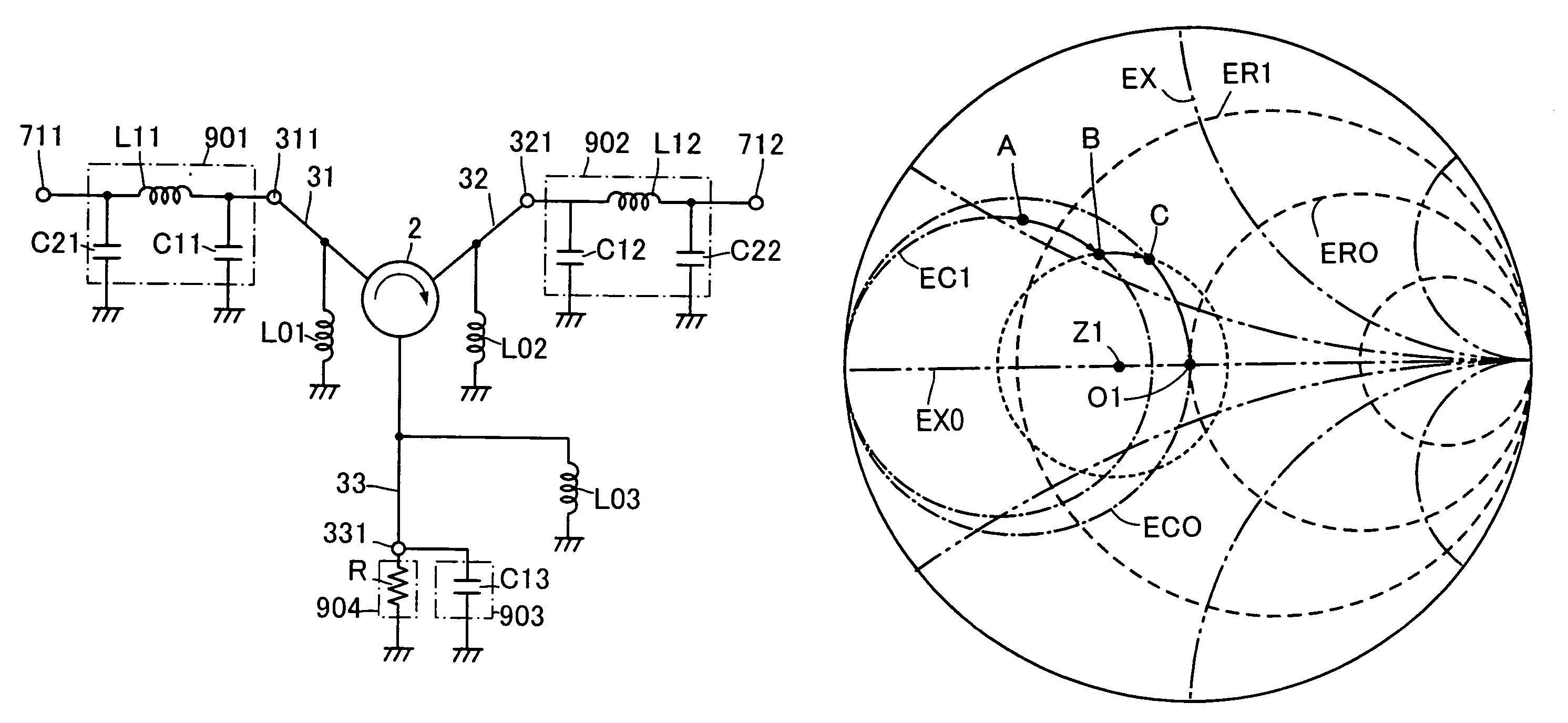
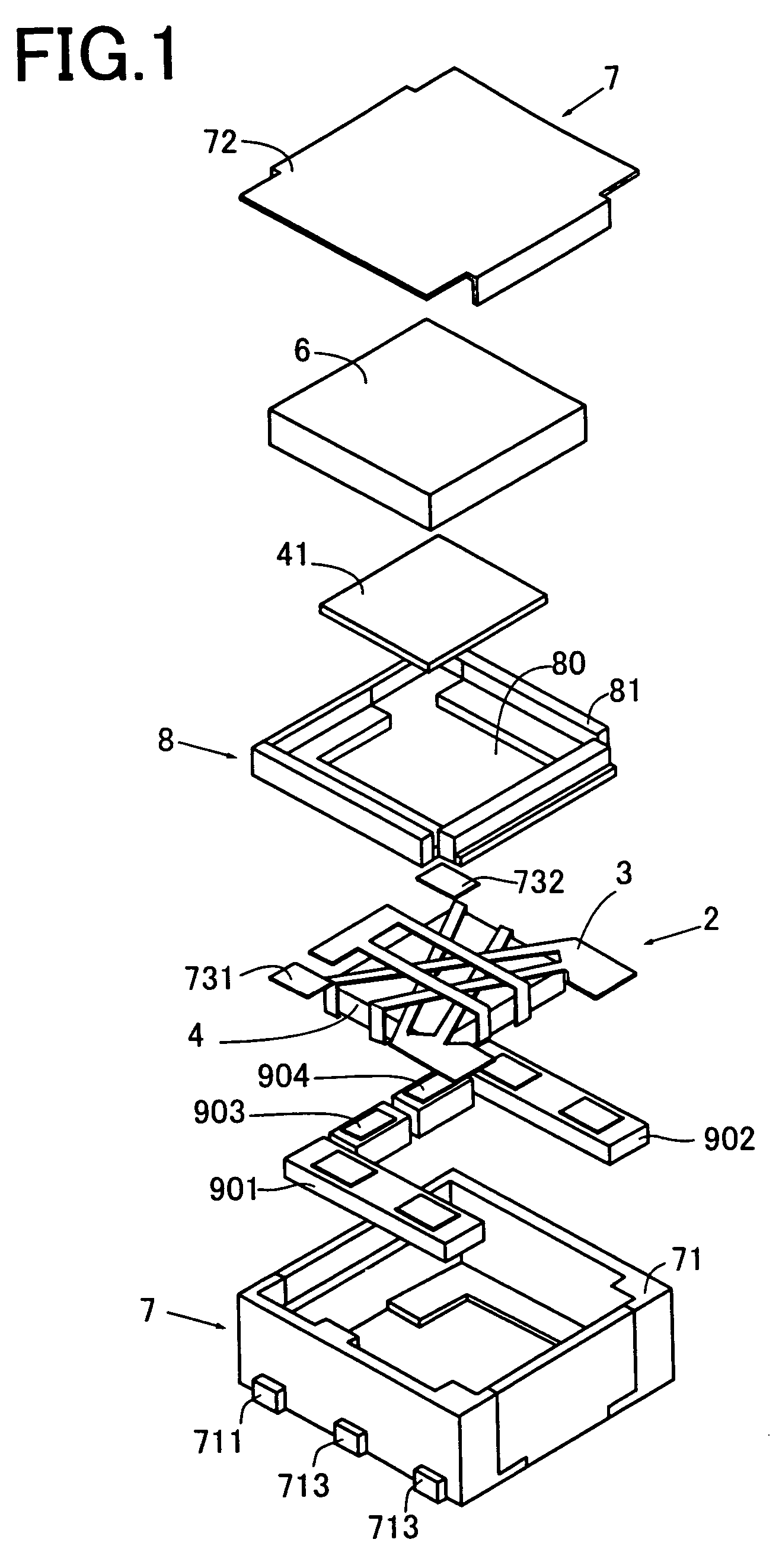
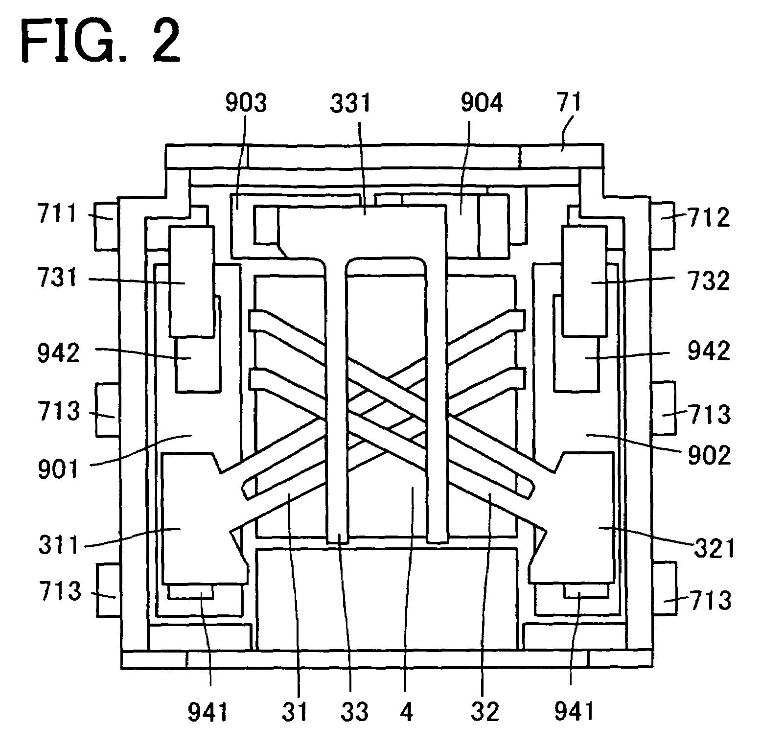
[0036]FIG. 1 is an exploded perspective view of a non-reciprocal device embodying the invention, FIG. 2 is a flat view of a gyromagnetic component of the non-reciprocal device shown in FIG. 1 for illustrating its assemblage, and FIG. 3 is the circuit diagram of the non-reciprocal device shown in FIGS. 1 and 2.

[0037]The non-reciprocal device 1 shown in the figures comprises a gyromagnetic component 2, a permanent magnet 6, a case 7, a pressing member 8, and electric components 901, 902, 903, 904.

[0038]The case 7 comprises an enclosure member 71 and a lid member 72. The enclosure member 71 comprises electrically conductive magnetic metal partitions and insulating resin partitions, has a shape like a box whose top is open, and has its bottom grounded (ground G potential). Each of the insulating partitions has terminals 711–713 for connecting internal circuit elements with external circuit elements. The enclosure member 71 houses the gyromagnetic component 2, permanent magnet 6, electri...


PUM


Abstract

The present invention is directed to a non-reciprocal device whose use makes it possible to reduce the insertion loss, and the size and thickness of its body, and broaden the frequency band treated by it. The DC magnetic field is adjusted such that, in a Smith chart where the center O1 represents the normalized impedance, the impedance of the gyromagnetic component 2 is positioned at a value which is on a constant conductance circle smaller than the reference constant conductance circle EC0 passing the center O1 and which is on a constant reactance line above the reference constant reactance line EX0 passing the center O1. Inductor L11 or L12 has one end connected to a terminal of the center conductor such that in the Smith chart, the impedance of the gyromagnetic component 2 seen from the other end of the inductor L11 or L12 is positioned at a value which is on the reference constant conductance circle EC0 passing the center O1. First capacitor C21 or C22 is connected, in parallel with the center conductor, to the other end of the inductor L11 or L12 such that in the Smith chart, the impedance of the gyromagnetic component 2 seen through the inductor from the connection point of the first capacitor is positioned at a value which is on the center O1.

Description

TECHNICAL FIELD[0001]The present invention relates to a non-reciprocal device such as an isolator, circulator, etc.BACKGROUND OF THE INVENTION[0002]A non-reciprocal device such as an isolator or circulator is incorporated, for example, in a mobile wireless communication device such as a mobile telephone set. A typical non-reciprocal device comprises magnetic components such as a gyromagnetic component formed from a soft ferrite body and center conductors and a permanent magnet, and electric components such as a matching capacitor and a terminal resistance, all housed in a magnetic-metal case functioning as a yoke.[0003]The center conductors are combined with the soft ferrite body, and to the assembly is applied a DC magnetic field by the permanent magnet. Each of the center conductors has one end placed on one surface of the soft ferrite body to be connected to the metal case serving as a grounding part to be grounded, and the other end arranged on the other surface of the soft ferr...

Claims


Application Information

Patent Timeline
Patent Type & Authority Patents(United States)
IPC IPC(8): H01P1/383H01P1/36H01P1/387
CPCH01P1/387
Inventor SAKAI, MINORU
Owner TDK CORPARATION
Why Eureka
Try Eureka