
Turbine nozzle segment cantilevered mount

A nozzle and plate segment technology applied in the field of cantilever-mounted nozzle segments

Active Publication Date: 2004-09-01
GENERAL ELECTRIC CO
View PDF2 Cites 7 Cited by
  • Summary
  • Abstract
  • Description
  • Claims
  • Application Information

AI Technical Summary

Problems solved by technology

This causes the nozzle segment to rotate about a radial line perpendicular to the central axis of the engine and turbine, creating considerable challenges to the installation and sealing of individual vanes as well as other cantilevered nozzle segments, especially with respect to deviation from the outer band Plate-to-Substrate Synthetic Gas Load Vectors for Nozzle Segment Challenges

Method used


Image

  • Turbine nozzle segment cantilevered mount
  • Turbine nozzle segment cantilevered mount
  • Turbine nozzle segment cantilevered mount

Examples


Embodiment Construction

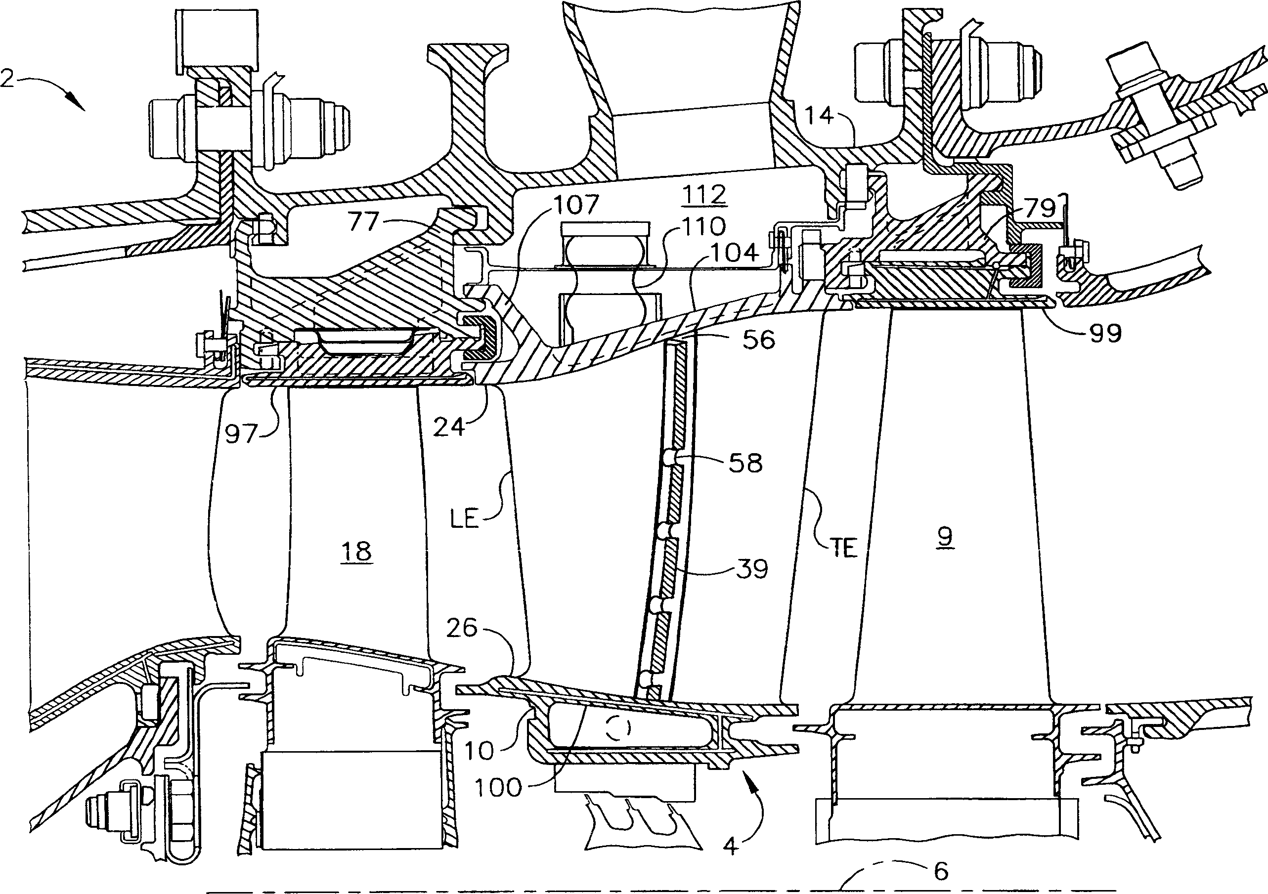
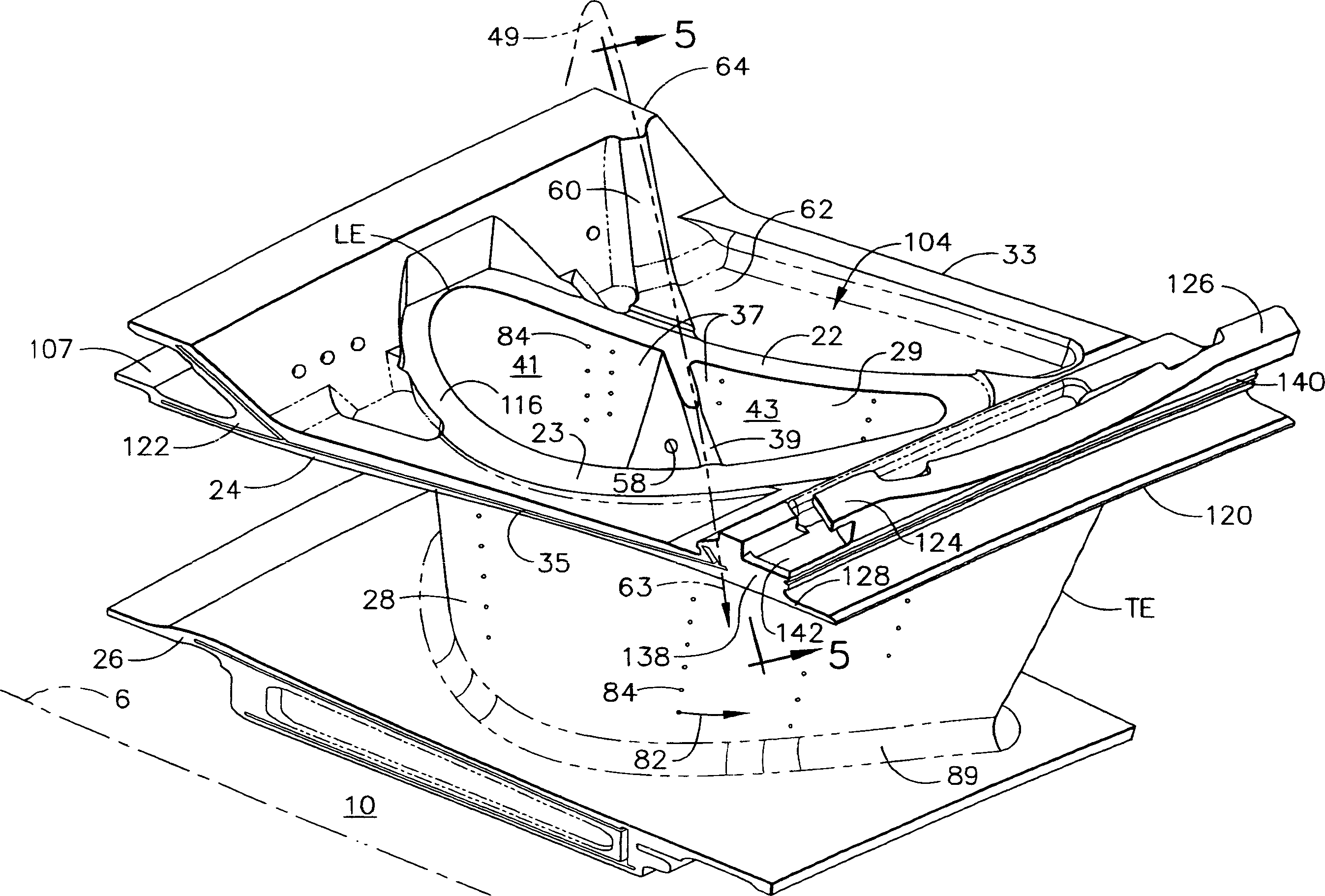
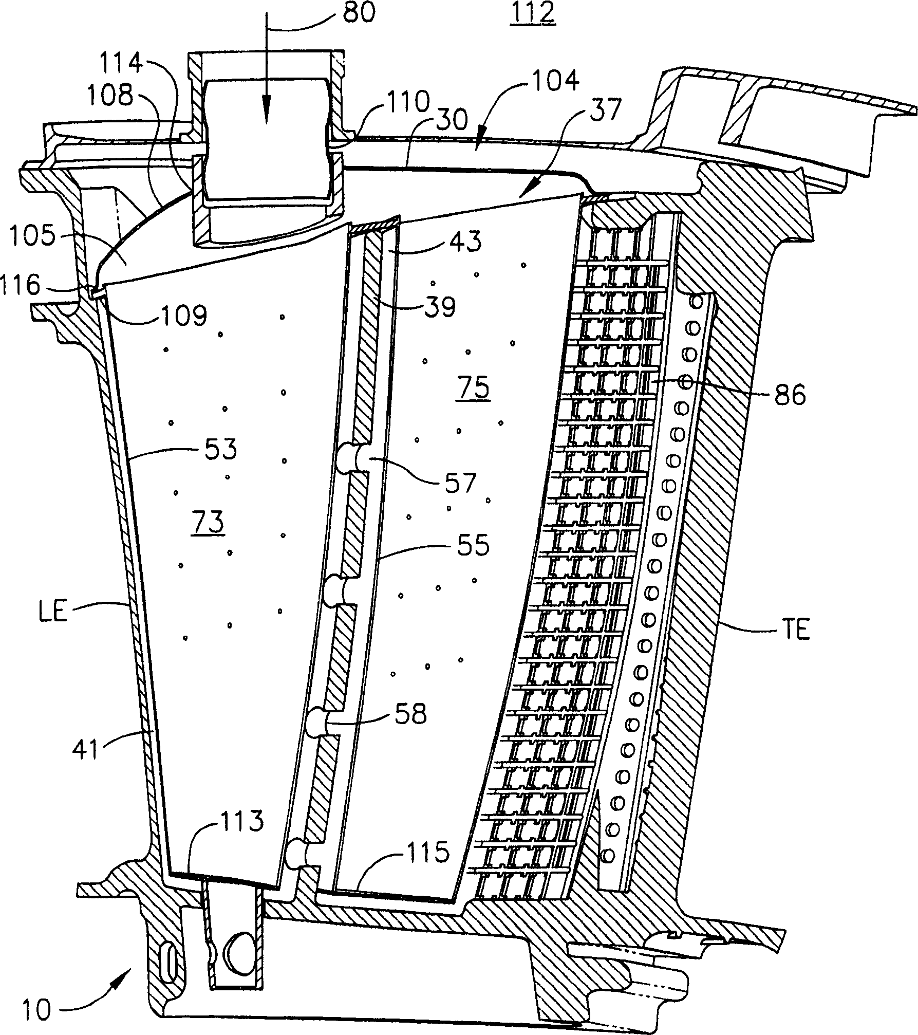
[0024] figure 1 An exemplary second stage turbine nozzle 4 of a high pressure turbine 2 of an aircraft gas turbine according to the present invention is shown in FIG. The nozzle 4 is arranged around a longitudinal or axial center axis 6 and comprises an annular housing 14 from which a plurality of nozzle segments 10 are mounted cantilevered. The nozzle section 10 is arranged between the rotor blades 18 of the first stage of the high-pressure turbine of the immediately upstream row and the rotor blades of the second stage of the turbine of the immediately downstream row 9 . First and second shrouds 97, 99 surround the first and second stage turbine rotor blades 18 and 9, respectively, and are supported by first and second shroud supports 77 and 79, which extend along the Radially inwardly is suspended by and connected to an annular housing 14 . The nozzle segment 10 is hooked to the first shroud support 77 by forward hooks 107 and cantilevered from the second shroud support 7...


PUM


Abstract

A turbine nozzle segment includes at least one hollow airfoil extending radially between radially outer and inner band segments, a clockwise open hook on a clockwise end at an aft end of the outer band segment, and counter-clockwise open hook on a counter-clockwise end at the aft end of the outer band segments. An exemplary embodiment of the turbine nozzle segment includes a load stop extending radially outwardly from the outer band segment. At least one aftwardly facing load face is at the aft end of the nozzle segment at the outer band segment. The clockwise open hook is C-shaped and the counter-clockwise open hook is a shiplap hook. Another embodiment of the turbine nozzle segment has only one hollow airfoil with an airfoil wall surrounding a bifurcated cavity divided into forward and aft cavities by a bifurcating rib extending between pressure and suction sides of the airfoil wall.

Description

technical field [0001] This invention relates to the installation of gas turbine engine turbine nozzle segments and, in particular, to cantilevered mounting for such nozzle segments. Background technique [0002] In a conventional gas turbine engine, air is compressed in a compressor and mixed with fuel in a combustor where it is ignited and combusted to produce hot gas. The generated gas flows down through a high pressure turbine (HPT) having one or more stages comprising one or more HPT turbine nozzles and rows of HPT rotor blades. The gas then flows to a low pressure turbine (LPT), which typically includes multiple stages with corresponding LPT turbine nozzles and LPT rotor blades. [0003] The HPT turbine nozzle includes a plurality of circumferentially spaced fixed hollow nozzle vanes secured between radially outer and inner band plates (or bands). Typically a single chamber impingement baffle is inserted into each hollow airfoil to provide cooling air to the airfoil....

Claims


Application Information

Patent Timeline
Patent Type & Authority Applications(China)
IPC IPC(8): F01D9/02F01D5/18F01D9/04F01D25/24F02C7/18
CPCF05B2240/12E05Y2900/402F01D25/246F05B2260/30F05B2260/2241B22C21/14F05B2260/201F05B2240/801Y02T50/676Y02T50/67F01D5/189F01D9/041F05D2240/12F05D2260/201F05D2260/22141F05D2260/30F05D2240/81Y02T50/60
Inventor A·C·波维斯R·E·小麦克雷J·P·克拉克J·J·彼得曼R·A·弗雷德里克E·E·吉布勒B·D·凯斯
Owner GENERAL ELECTRIC CO
Learn More