A dynamic detecting and compensating method for faulty pixel

A technology of dynamic detection and compensation method, applied in image enhancement, image data processing, instruments, etc., can solve the problems of image quality degradation, large amount of calculation, increased complexity, etc., and achieve the effect of small degradation of image quality

Inactive Publication Date: 2004-09-01
VIMICRO CORP
View PDF0 Cites 24 Cited by
  • Summary
  • Abstract
  • Description
  • Claims
  • Application Information

AI Technical Summary

Problems solved by technology

Although this approach seems very reasonable, the calculation of averaging each surrounding pixel is very large, which increases the complexity of the calculation; and averaging a large number of pixels is actually equivalent to using

Method used


Image

  • A dynamic detecting and compensating method for faulty pixel
  • A dynamic detecting and compensating method for faulty pixel
  • A dynamic detecting and compensating method for faulty pixel

Examples


Embodiment Construction

[0023] In the following description, well-known functions or technologies will not be described in detail to avoid unnecessary confusion with the content of the present invention.

[0024] Figure 1 is a schematic diagram of a 5×5 pixel array, we set the value of the middle pixel to be P m,n , where m represents the number of rows and n represents the number of columns. P m,n It can be R, G, or B. Here, the treatment of R, G, or B is equally applicable. According to the principle of digital image, the value P m,n only with P m-2,n ,P m,n ,P m+2,n ,P m,n-2 ,P m,n+2 related.

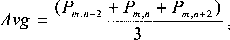
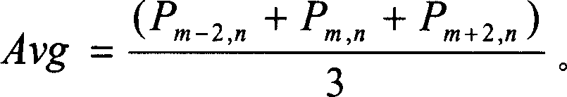
[0025] Fig. 2 is a schematic flow chart of the method of the present invention, as shown in the figure, when the pixel point P m,n When performing detection, first select the point P related to it m-2,n ,P m,n ,P m+2,n ,P m,n-2 and P m,n+2 , calculate the current pixel point P m,n The relative pixel brightness difference values ​​DH and DV in the horizontal and vertical directions, where:

...


PUM


Abstract

The invention discloses a method for measuring and compensating the deficient image element in digital image outputted by image sensor, which includes following steps: at first, works out the difference of brightness between the current image element and the relative image elements in parallel and vertical directions; secondly, determines the efficient direction according to the absolute value of the two different values; works out the brightness average of relative image element in the direction, and the parameter Var; compares the Var and a preset noise threshold T; finally, compensates them according to the judging result. By using the invention, the memory and the control unit can be saved, and it can measure the deficiency image element which occurs after being sold and not recorded in the memory.

Description

[0001] Field [0002] The invention belongs to the field of digital image processing, in particular to a method for dynamically detecting and compensating defective pixels in a digital image output by an image sensor. technical background [0003] The photosensitive device in the digital image input device is an array composed of many interconnected photosensitive units, which converts light signals into electrical signals. Generally speaking, these photosensitive devices are not perfect, and there will be some defective photosensitive cells. Therefore, its output image may contain some abnormal pixels. In order to control the production cost within an acceptable range, these optical sensors allow a certain number of defective pixels to exist, but the sensor manufacturer must provide the information of the defective pixels to the camera manufacturer before selling the sensor. The most popular method at present is that the location information of defective pixels is stored in...

Claims


Application Information

Patent Timeline
IPC IPC(8): G06T5/50
Inventor 俞青王浩赵原
Owner VIMICRO CORP
Why Eureka
Try Eureka