Compressor

A compressor and refrigerant gas technology, applied in the field of compressors, can solve the problems of increased compressor volume, inability to effectively reduce refrigerant gas pulsation pressure, refrigerant gas pulsation pressure limitation, etc.

Inactive Publication Date: 2004-09-08
HANON SYST
View PDF1 Cites 3 Cited by
  • Summary
  • Abstract
  • Description
  • Claims
  • Application Information

AI Technical Summary

Problems solved by technology

[0017] However, in this prior art, when the refrigerant gas is discharged from the front casing to the outside of the compressor, since the pulsation pressure of the refrigerant gas cannot be effectively reduced, the decrease in the pulsation pressure of the

Method used


Image

  • Compressor
  • Compressor
  • Compressor

Examples


Embodiment Construction

[0043] Reference will now be made in detail to the preferred embodiments of the invention, examples of which are illustrated in the accompanying drawings.

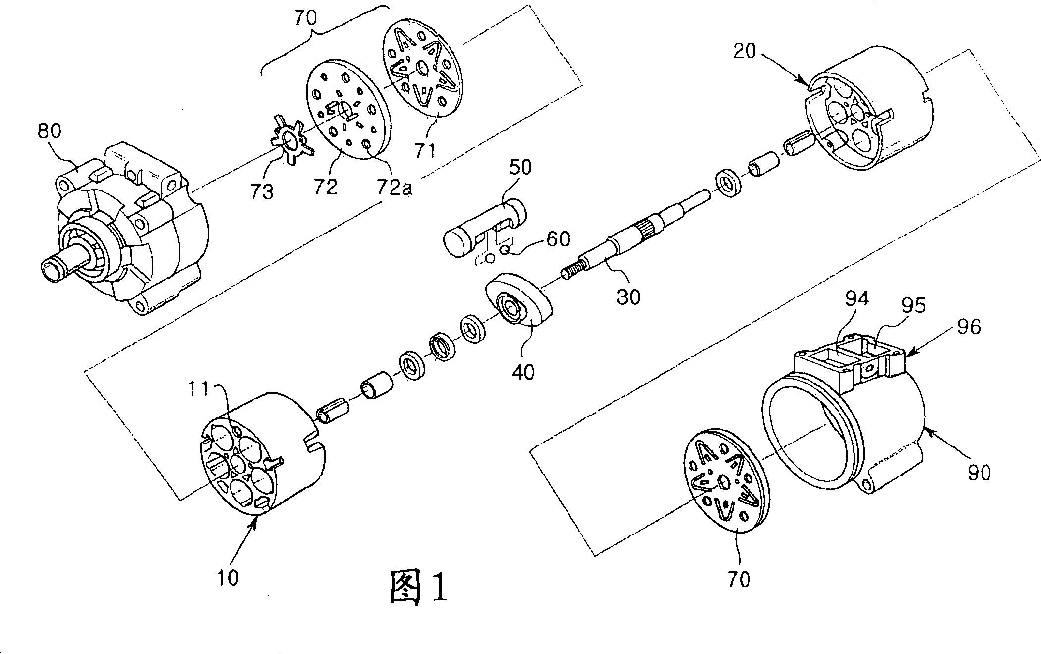
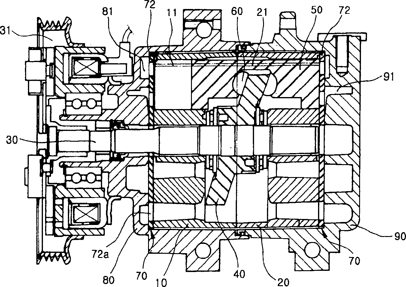
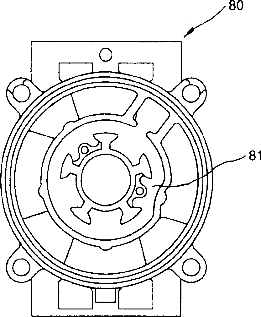
[0044] Figure 6 It is a side view of the compressor of the first embodiment of the present invention; Figure 7 for Figure 6 Side cutaway view of the compressor shown; Figure 8 for Figure 6 Front view of the front casing employed in the compressor shown; Figure 9 for Figure 6 Front view of the back casing employed in the compressor shown.

[0045] In the first embodiment of the present invention, as Figure 6 and 7 As shown, the compressor includes: a front housing 200 closing one end of the front cylinder body 400; a rear housing 300 closing one end of the rear cylinder body 500; and a front cylinder arranged to be combined with each other between the front housing 200 and the rear housing 300 Body 400 and rear cylinder block 500; drive shaft 600 rotatably supported in front cylinder block 400 and rear cylin...


PUM


Abstract

The present invention relates to a compressor that can reduce the refrigerant gas pulsation pressure in multi-step when a refrigerant gas is discharged into a rear refrigerant gas discharge chamber toward the outside of the compressor and into a front refrigerant gas discharge chamber toward the outside of the compressor, thereby obtaining excellent reduction in the refrigerant gas pulsation pressure and remarkably reducing a noise due to the refrigerant gas pulsation.

Description

technical field [0001] The present invention relates to a compressor, especially a compressor capable of effectively reducing the pulsating pressure of refrigerant gas when discharging refrigerant gas. Background technique [0002] The compressor used in the air conditioning system of a motor vehicle can selectively receive the engine power transmitted by the pulley through the intermittent action of the electromagnetic clutch, and suck the refrigerant gas from the evaporator into it, and compress the refrigerant gas to compress the refrigerant gas The compressed refrigerant gas is discharged to the condenser. Compressors are divided into different types according to the compression structure, and the type widely used in motor vehicles is the swash plate compressor. [0003] 1 to 4 show the structure of a conventional swash plate compressor. [0004] As shown in FIGS. 1 and 2, a general swash plate type compressor is constructed in such a manner that a swash plate 40 on wh...

Claims


Application Information

Patent Timeline
IPC IPC(8): F04B11/00F04B27/10F04B39/00
CPCF04B27/1081F04B39/0055F04B11/00
Inventor 黄承溶朴泰英
Owner HANON SYST
Why Eureka
Try Eureka