
Gas-liquid separator for sealing compressor

A technology of gas-liquid separator and compressor, which is applied in the direction of machines/engines, liquid variable displacement machines, rotary piston machines, etc., and can solve problems such as damage

Inactive Publication Date: 2004-09-08
LG ELECTRONICS INC
View PDF0 Cites 7 Cited by
  • Summary
  • Abstract
  • Description
  • Claims
  • Application Information

AI Technical Summary

Problems solved by technology

Therefore, the welded part is easily damaged by vibration or other effects

Method used


Image

  • Gas-liquid separator for sealing compressor
  • Gas-liquid separator for sealing compressor
  • Gas-liquid separator for sealing compressor

Examples


Embodiment Construction

[0031] Reference will now be made in detail to preferred embodiments of the invention, examples of which are illustrated in the accompanying drawings.

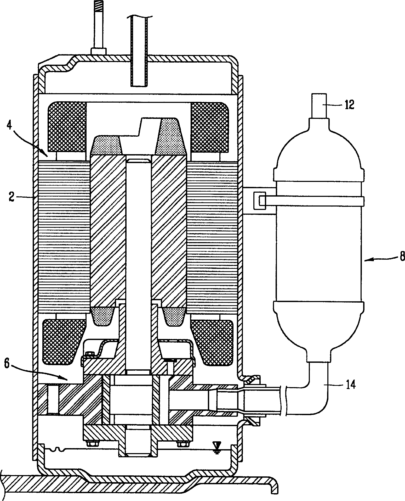
[0032] figure 2 It is a cross-sectional view of a hermetic compressor equipped with a gas-liquid separator of the present invention.

[0033] The hermetic compressor of the present invention comprises: a hermetic shell 2 with a constant space; a drive unit 4 mounted on one side of the shell 2 for generating rotational force; A compression unit 6 that compresses the refrigerant with a driving force;

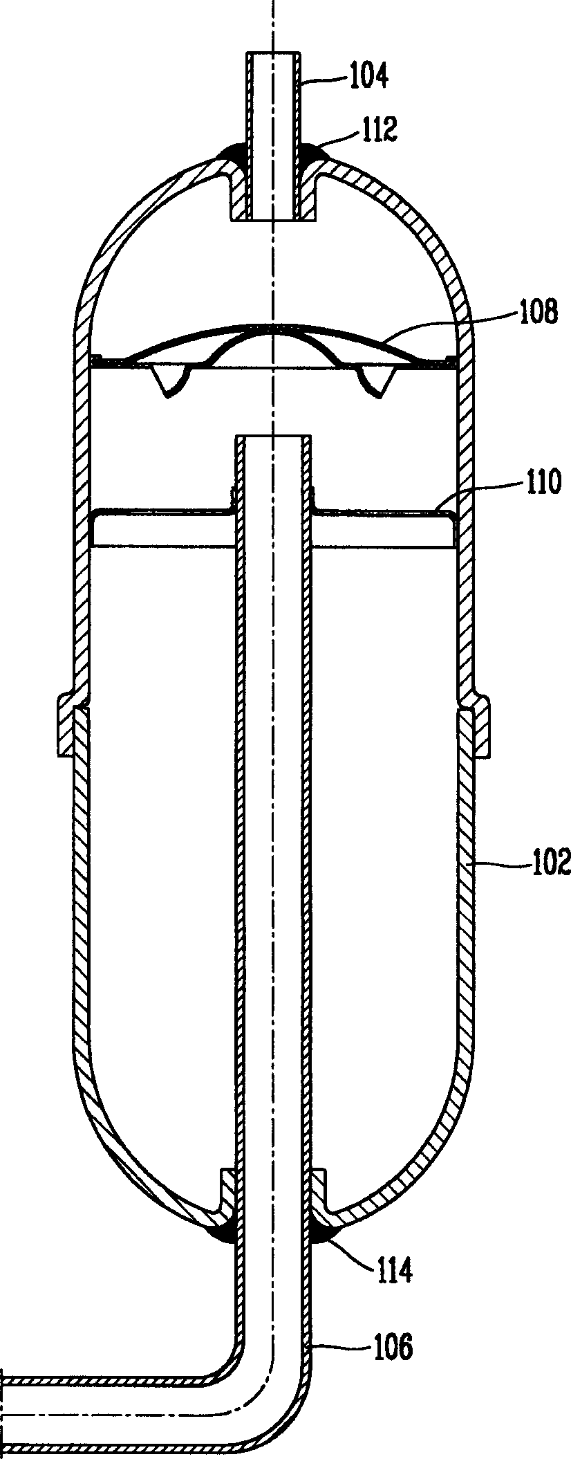
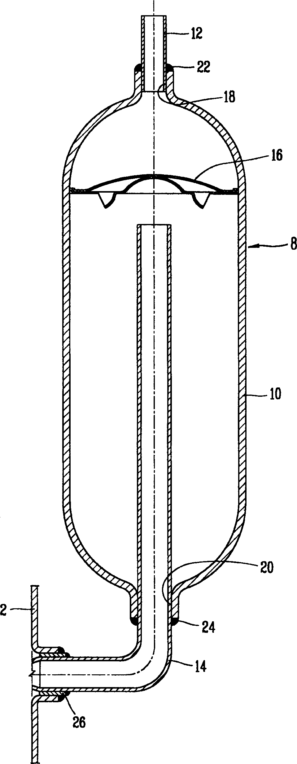
[0034] Such as image 3 As shown, the gas-liquid separator 8 includes: a housing 10 having a constant space for guiding the refrigerant; a suction pipe 12 sealingly connected to the top side of the housing 10 for guiding the refrigerant into the housing 10; and A discharge pipe 14 inserted into the casing 10 at a constant length from the bottom side of the casing 10 is connected to the compressor casing 2 to introduce gas refr...


PUM


Abstract

An accumulator of an enclosed compressor comprises a case having a predetermined space; a suction pipe welded to the upper part of the case, to suck a refrigerant into the case; and a discharge pipe welded to the lower part of the case and connected to a compressor casing. At least one of a weld portion of the suction pipe and the upper part of the case and a weld portion of the discharge pipe and the lower part of the case is welded with phosphor bronze.

Description

technical field [0001] The present application relates to a gas-liquid separator of a hermetic compressor, in particular, to a gas-liquid separator of a hermetic compressor capable of reducing production cost, preventing leakage of welded parts and improving production efficiency. Background technique [0002] Generally, a gas-liquid separator is installed on a refrigerant suction pipe of the compressor, so as to prevent liquid refrigerant from entering the compressor. [0003] figure 1 is a sectional view of a prior art gas-liquid separator. [0004] A conventional gas-liquid separator includes: a sealed housing 102 with a constant space; a suction pipe 104 that is sealingly connected to the top side of the housing 102 for guiding refrigerant into the housing 102; The bottom side is inserted into the casing 102 into a discharge pipe 106 for supplying gaseous refrigerant evaporated in the casing 102 to a compressor body (not shown). [0005] In addition, a screen 108 is m...

Claims


Application Information

Patent Timeline
IPC IPC(8): F04B39/00F25B43/00
CPCF04B39/12F04B39/14F04C18/356F04C2230/231
Inventor 高贤准
Owner LG ELECTRONICS INC
Learn More