
Method for manufacturing magnetic control overtravel-limit switch

A travel switch, switch box technology, applied in magnetic/electric field switches, electrical switches, electrical components, etc., can solve problems such as easy failure, and achieve the effect of extending the service life

Inactive Publication Date: 2004-09-15
赵为民
View PDF0 Cites 3 Cited by
  • Summary
  • Abstract
  • Description
  • Claims
  • Application Information

AI Technical Summary

Problems solved by technology

If it is used to control a load of 380V above 1A, it is prone to failure

Method used


Image

  • Method for manufacturing magnetic control overtravel-limit switch
  • Method for manufacturing magnetic control overtravel-limit switch

Examples


Embodiment Construction

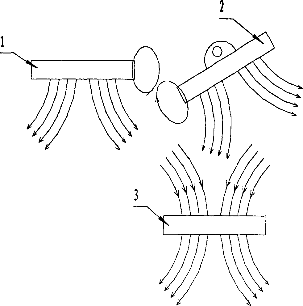
[0010] figure 1 In the figure, the arc with the arrow represents the magnetic force line, and the direction of the arrow is the direction of the magnetic force line. The fixed magnet (1) is fixed, and the rotatable magnet (2) can rotate around the rotating shaft. The direction of the magnetic force line is consistent with that of the fixed magnet (1). The directions of the magnetic force lines adjacent to the fixed magnet (1) and the rotating magnet (2) are also the same, so that the adjacent parts of the two magnets are always in a state of repulsion, as shown in the figure, the rotating magnet (2) is pushed by the repulsive force to reverse The hour hand turns. The execution magnet (3) is consistent with the direction of the magnetic force lines of the fixed magnet and the rotating magnet, the magnetic field strength is two to three times greater than that of the fixed magnet (1) and the rotating magnet (2), and it moves parallel to the fixed magnet, as shown in the figure, ...


PUM


Abstract

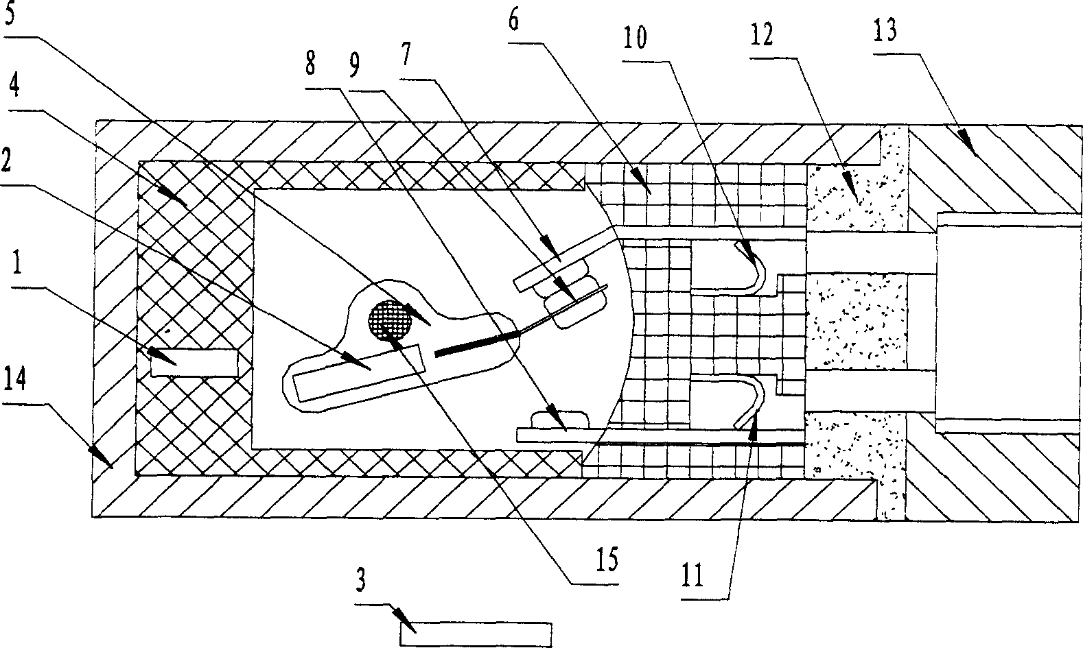
Basic principle is as following: three pieces of rare earth permanent magnet iron are fixed in certain combination mode, and magnetic force is utilized to control on / off switch unit and keep contact reliability of switch contacts. steps include: one magnet iron is inlaid in quadrate insulating bush, and second piece of magnet iron combined with a rotatable moving contact is installed inside switch box with normal open and normal close contacts being inlaid. The said switch box is embedded to the insulating bush, and pins are as connecters leaded out. Assembled insulating bush is installed inside aluminum alloy case. Third magnet iron is connected to movable part of mechanism, moving in parallel to the case with distance 2-10 mm. magnet iron outside case plays function of trigger switch. Glue is filled inside switching part so that the product can be used in condition of inflammable gas and dust such as power plant, coal mine and oil field.

Description

[0001] Field [0002] The invention relates to a method for using magnetic force to trigger and maintain a switch action, in particular, utilizing the repulsion between two magnetic fields to maintain the tightness of contact combination. technical background [0003] At present, the known limit switches and travel switches all use the form of mechanical collision to trigger the switch action. The disadvantage is that every time the switch is triggered, there will be a certain impact on the switch. If the adjustment is not proper, the travel switch will be damaged if the impact force is slightly larger. . In addition, its mechanical transmission part is easy to wear and difficult to seal, especially in high dust and open air environments, which will aggravate wear and cause water and dust to enter and damage the travel switch. However, the current magnetic control proximity switch of the reed type is to encapsulate two magnetic reeds in parallel in a glass tube. Breaking und...

Claims


Application Information

Patent Timeline
Patent Type & Authority Applications(China)
IPC IPC(8): H01H11/00H01H36/00
Inventor 赵为民
Owner 赵为民
Learn More