Power changing device

A power conversion device and power converter technology are applied in the output power conversion device, DC power input is converted into DC power output, and irreversible DC power input is converted into AC power output, etc. Problems such as increased switching loss

Inactive Publication Date: 2004-09-15
MITSUBISHI ELECTRIC CORP
View PDF1 Cites 11 Cited by
  • Summary
  • Abstract
  • Description
  • Claims
  • Application Information

AI Technical Summary

Problems solved by technology

[0005] However, the above-mentioned power conversion device has a sampling value compensator to remove the ripple component contained in the current detection value, and the current average value obtained by the sampling value compensator is used as the control object. Therefore, there is a problem that even if the current detection value changes rapidly, , the sampling value compensator also needs to be averaged, and cannot get enough high-speed effects
Since the PWM signal is a signal to drive the power switching element in the power converter, if the pulse increases, the switching times of the power switching element will increase, resulting in an increase in switching loss. Therefore, there is a problem that a power switching element with a large rated capacity must be used.

Method used


Image

  • Power changing device
  • Power changing device
  • Power changing device

Examples


Embodiment 1

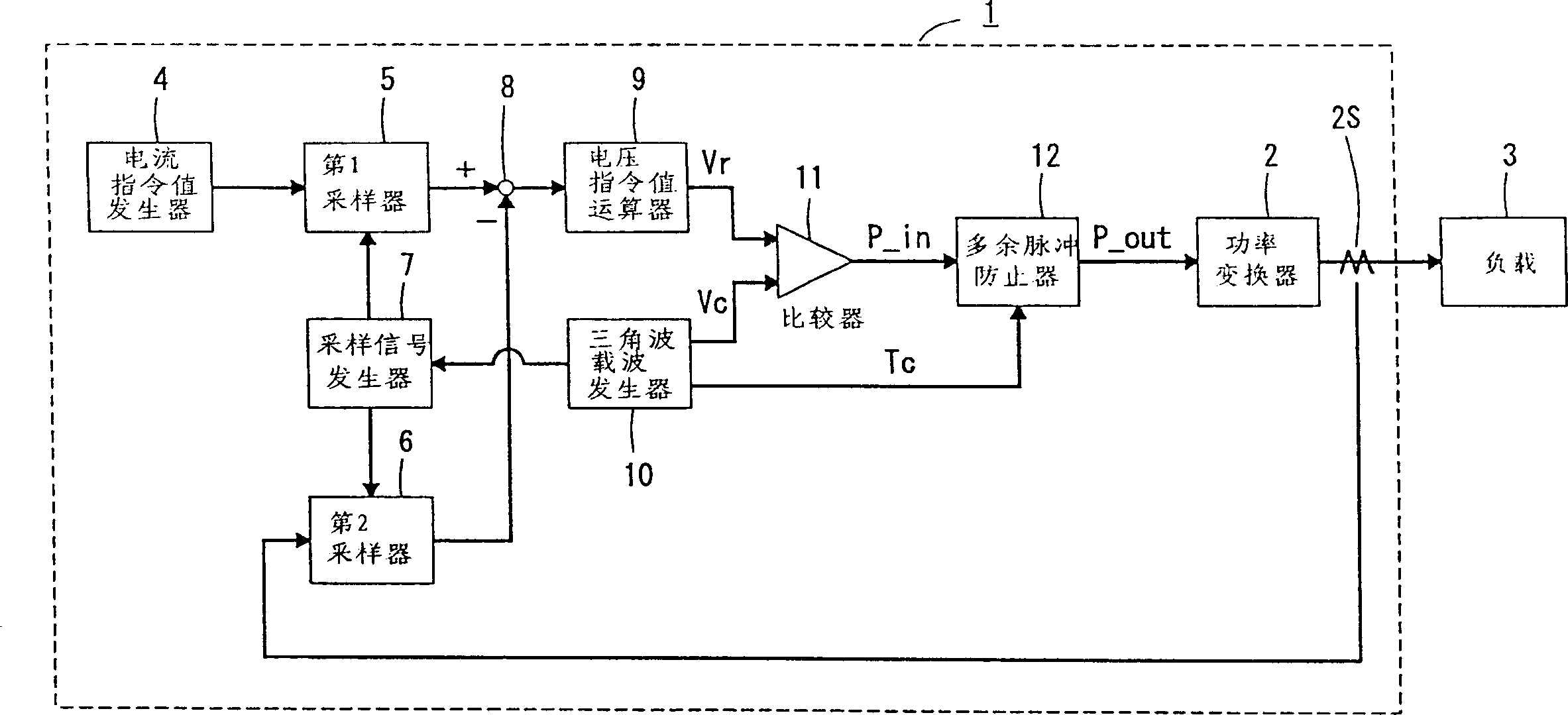
[0046] The following is based on figure 1 The shown block diagram illustrates a power conversion device according to an embodiment of the present invention.

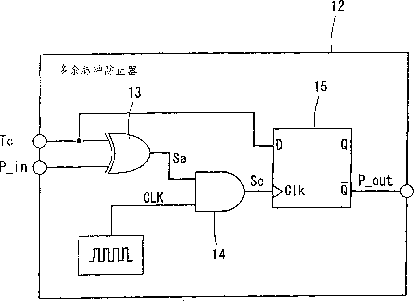
[0047] exist figure 1 Among them, the power conversion device 1 includes a power converter (power conversion device) 2 having a power switching element such as a transistor, and a current command value generator 4 serving as a current command value generator for generating a current command value of the power converter 2, which converts power The first sampler (first sampling device) 5 that samples the first current command value of the converter 2 and simultaneously outputs the second current command value detects the first current of the current detector 2s that detects the current flowing through the load 3 The second sampler (second sampling device) 6 that samples the value and outputs the second current detection value at the same time determines the sampling time of the first and second samplers 5 and 6, and sim...

Embodiment 2

[0059] The following is based on Figure 4 The block diagram of the power conversion apparatus shown illustrates other embodiments of the present invention. exist Figure 4 in, with figure 1 The same reference numerals denote the same or corresponding parts, and explanations thereof are omitted.

[0060] exist Figure 4 Among them, the second unnecessary pulse preventer 20 has an intersection detection device that detects the intersection of the first voltage command value generated from the voltage command value computing device 9 and the triangular wave carrier. A voltage command value suppressing device for generating a second voltage command value that suppresses changes in the first voltage command value without intersecting the triangular wave carrier again, and comparing the second voltage command value with the triangular wave carrier to generate the first PWM signal, and using the second voltage command value at the same time The 1PWM signal drives the comparator...

Embodiment 3

[0084] The following is based on the block diagrams of power conversion devices representing other embodiments Figure 9 Explain this description. exist Figure 9 in, with figure 1 The same reference numerals indicate the same or corresponding parts.

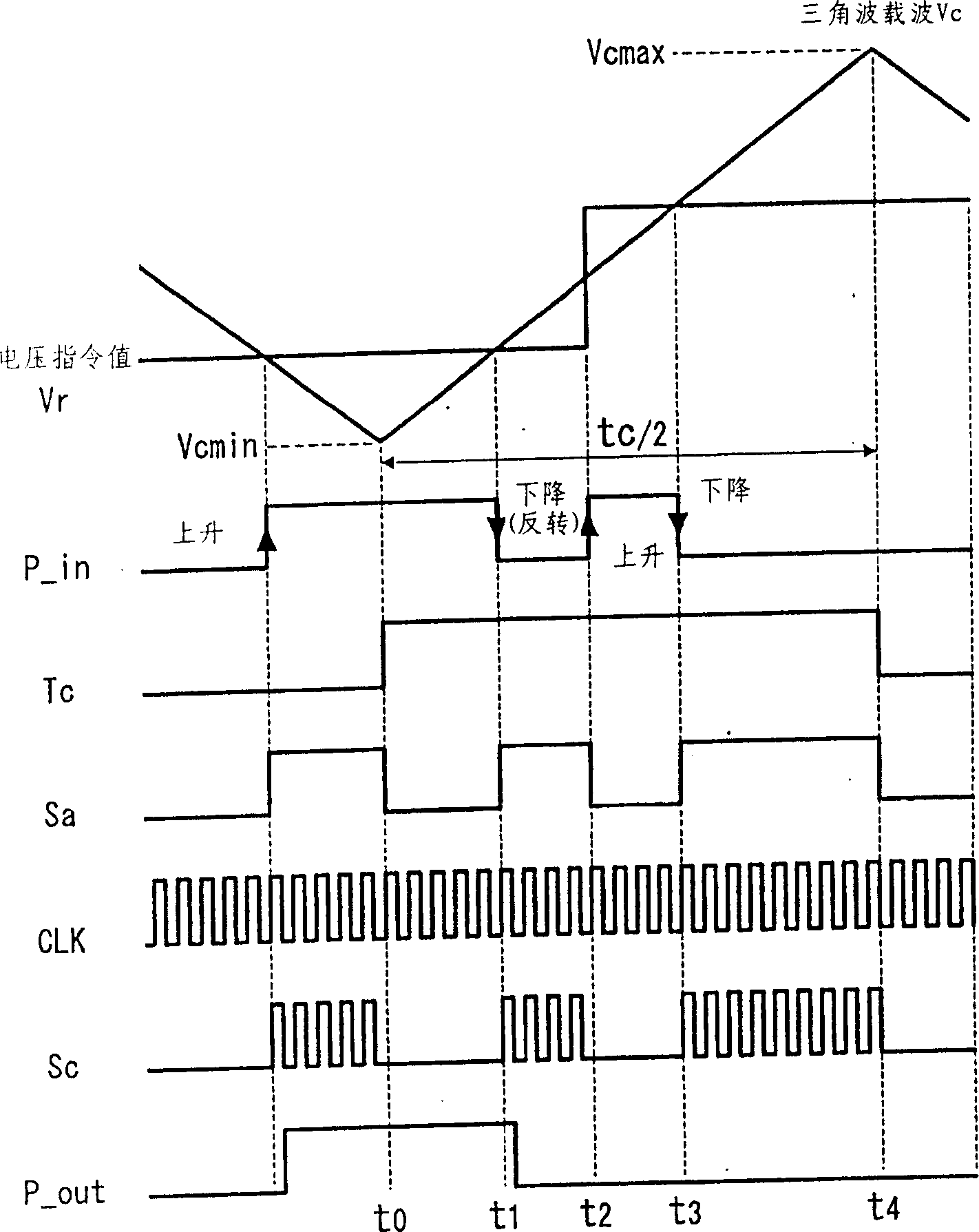
[0085] In Embodiment 1, since the first PWM signal is obtained by comparing the voltage command value Vr with the triangular wave carrier Vc, and the power converter 2 is driven by the second PWM signal that suppresses the inversion of the first PWM signal, the second PWM signal suppresses the first PWM signal. The redundant pulse portion of the 1PWM signal is removed from the command of the voltage command value Vr.

[0086] In this embodiment, while suppressing unnecessary pulses, the power converter is operated faithfully according to the voltage command value Vr.

[0087] exist Figure 7 and Figure 8 Among them, the voltage error compensator 21 obtains the three-pulse width difference ΔP(t) between the first PWM sign...


PUM


Abstract

A power converter comprises a first sampler (5) which samples a first current command value of the power converter (2) by the second period and generates a second current command value, a second sampler (6) which samples a first current detection value of a load (3) and generates a second current detection value, a voltage command value calculator (9) which calculates the voltage command value based on the second current command value and the second current detection value, and a comparator (11) which compares the second voltage command value with the triangular wave carrier and generates a first PWM signal, and a multi-pulsification preventer (12) having an inversion detecting means for detecting the inversion of the first PWM signal and an inversion suppressing means which drives the power converter (2) by a second PWM signal which is the first PWM signal whose inversion is suppresed according to the detection of the inversion detecting means.

Description

technical field [0001] The present invention relates to a power conversion device controlled by PWM (Pulse Width Modulation), and more particularly to a control device that detects a load current value driven by a power converter and performs feedback control on the current value so as to track the current command value. Background technique [0002] Conventional power conversion devices driven by PWM control calculate the voltage command value based on the load current command value and current detection value, compare the voltage command value with the triangular wave carrier, generate PWM pulses, and then use the PWM pulses to drive power converter to control the load. In this case, the instruction value and the detected value are sampled simultaneously in the same cycle, and the respective values ​​are read and sampled and held. [0003] However, since there is a pulsation component (current pulsation component) in the detected current value, according to Japanese Paten...

Claims


Application Information

Patent Timeline
Patent Type & Authority Applications(China)
IPC IPC(8): H02M1/08H02M3/157H02M3/335
CPCH02M3/33515H02M3/157H02M1/08H02M3/335H02M3/155H02M7/48
Inventor 吉田雅彦木全政弘井川康
Owner MITSUBISHI ELECTRIC CORP
Why Eureka
Try Eureka