Electric walking tillage machines

A tiller and electric motor technology, which is applied in the field of walking electric soil tillage machines, can solve the problems of not being able to show the installation position of the tiller, and achieve the effects of enhancing the linear driving ability and operability, reducing the burden, and reducing the burden

Inactive Publication Date: 2004-09-22
HONDA MOTOR CO LTD
View PDF1 Cites 4 Cited by
  • Summary
  • Abstract
  • Description
  • Claims
  • Application Information

AI Technical Summary

Problems solved by technology

Therefore, Japanese Patent Laid-Open Nos. HEI-6-98601 and HEI-10-136702 cannot show the installation position in the cultivator

Method used


Image

  • Electric walking tillage machines
  • Electric walking tillage machines
  • Electric walking tillage machines

Examples


Embodiment Construction

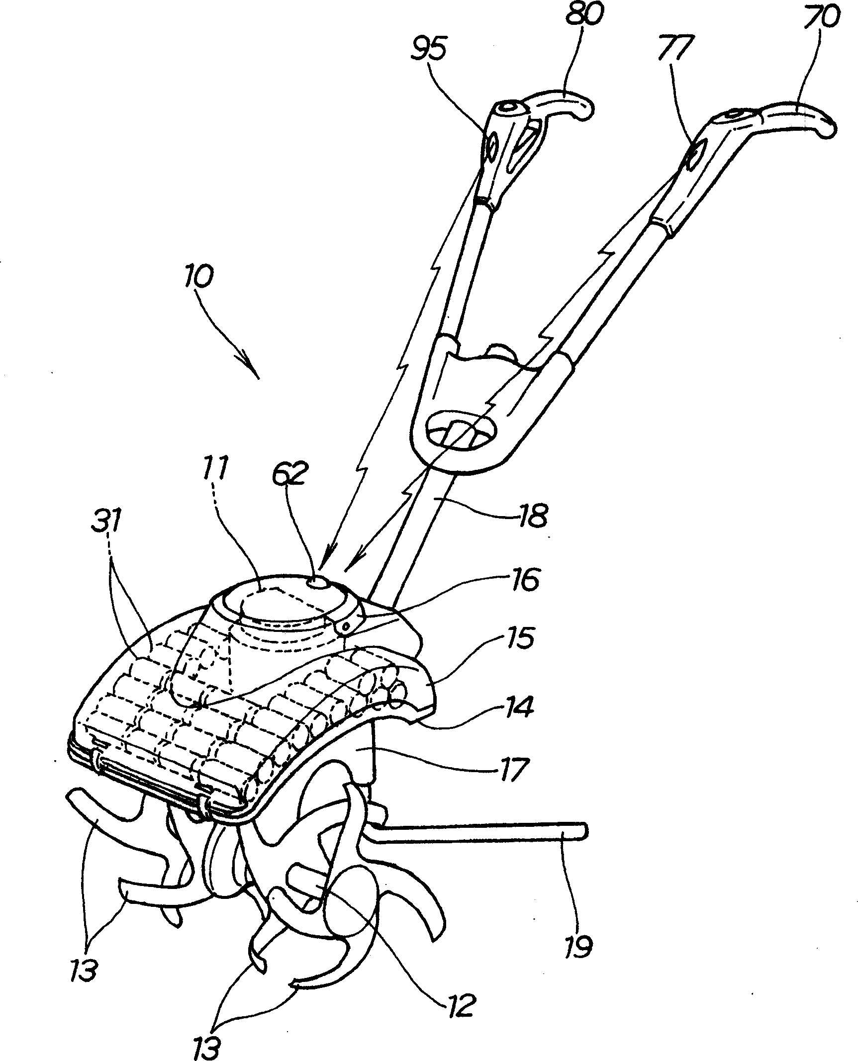
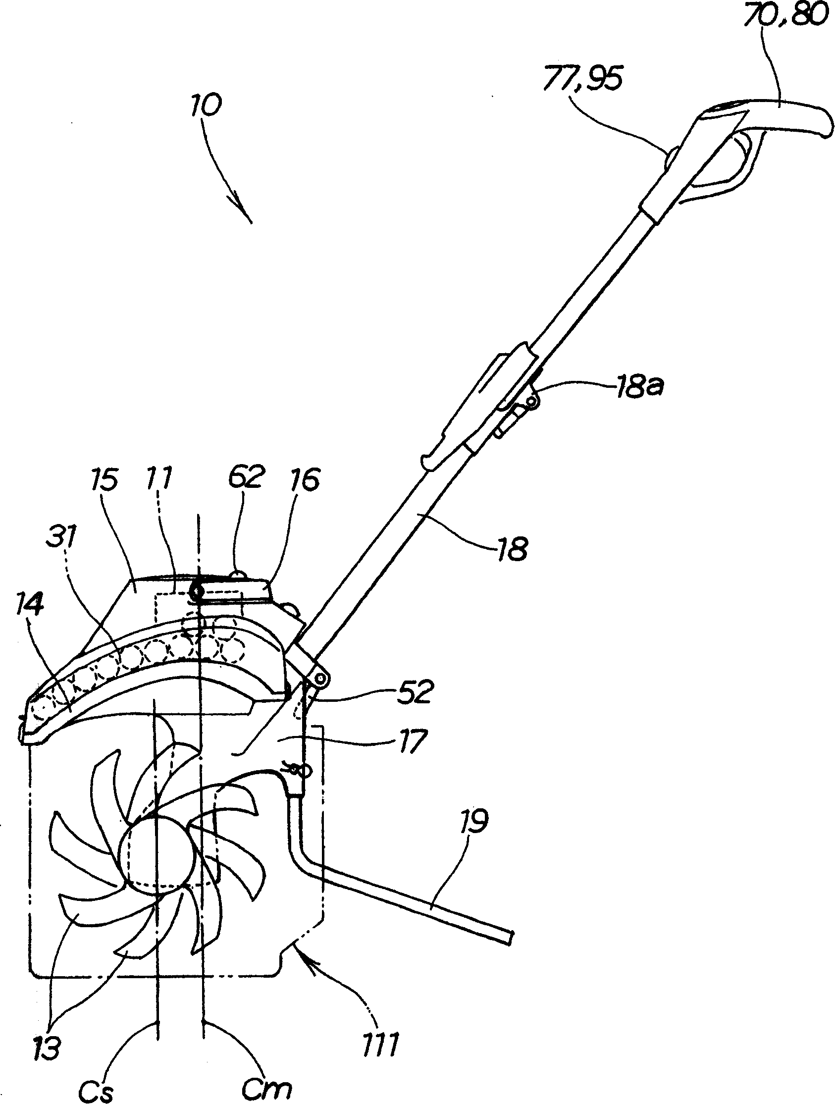
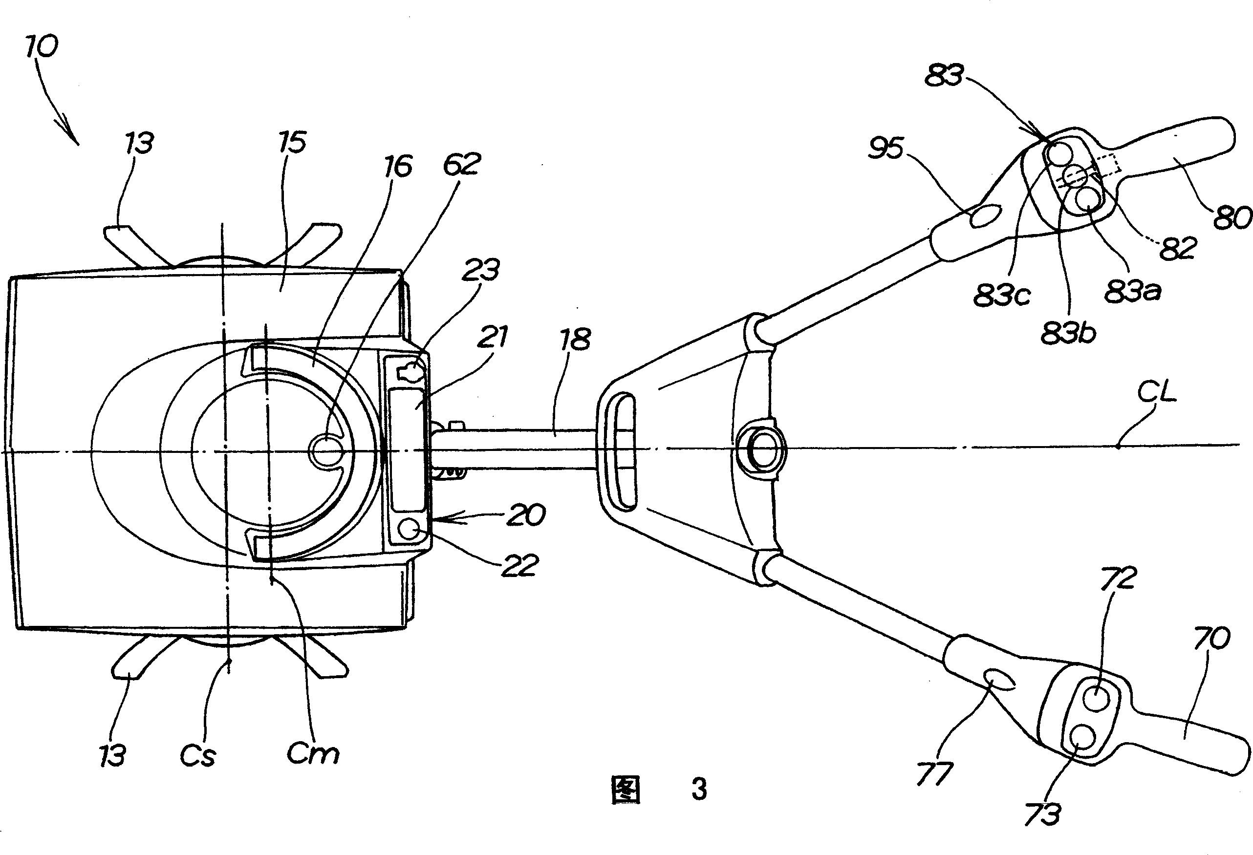
[0034] The walking electric tiller 10 is a self-propelled front-tooth tiller configured to transmit drive power from the motor 11 (ie, the drive source of the tiller 10) to the tiller shaft 12, through the left and right ends of the tiller shaft 12. Rotation of the plurality of tilling claws 13 at the top, so that the cultivator can travel on the cultivated land, and use the rotating tilling claws 13 to cultivate the land. The tilling claw 13 is covered with an upper baffle 14 , and the upper cover 15 covers the upper surface of the baffle 14 . The tillage shaft 12 is a rotating shaft extending horizontally (i.e. along the width direction of the body frame 17) between the opposite inner surfaces in the tiller body frame 17, and the baffle plate 14 is a casing designed mainly to prevent soil and Soil and sand scattered.

[0035] The electric tiller 10 is so small that an operator can carry it with his or her single arm by grabbing a carrying handle 16 provided on top of an upp...


PUM


Abstract

Walk-behind electric cultivating machine includes an electric motor provided and a plurality of batteries provided on an upper portion of a machine body frame, and a transmission mechanism and cultivating shaft mounted to a lower portion of the machine body frame. The cultivating shaft has a plurality of cultivating claws. The electric motor has a motor shaft extending downward, the transmission mechanism is positioned immediately below the motor shaft, and the plurality of batteries are positioned around and adjacent to the electric motor. The plurality of batteries and motor are positioned adjacent to the center of gravity of the machine practically immediately above the cultivating claws.

Description

technical field [0001] The invention relates to a walking electric soil tillage machine driven by an electric motor. Background technique [0002] A common walking (soil) tiller may also be called a "front-tine tiller", and such a front-tine tiller is configured to transmit driving force from a drive source, such as an engine, to a tiller shaft to The tiller can advance on the field through the rotation of the tilling claws arranged on the tilling shaft, and at the same time use the rotating tilling claws to plow the land. An improved front tooth cultivator using an electric motor instead of an engine as a driving source has been developed to reduce the burden on the operator by enhancing the operability of the cultivator and to improve the working environment (see, for example, Japanese Patent No. 3182930 and Japanese Patent No. 3182930 and Japanese Patent No. Publication Nos. HEI-6-98601 and HEI-10-136702). [0003] In the tiller disclosed in Japanese Patent No. 3182930,...

Claims


Application Information

Patent Timeline
Patent Type & Authority Applications(China)
IPC IPC(8): A01B33/02B62D51/06
CPCA01B33/028
Inventor 笹冈雅行福住泰美
Owner HONDA MOTOR CO LTD
Why Eureka
Try Eureka