

Multiblade collimator
A collimator and collimation technology, applied in the field of collimators, can solve problems such as error expansion, incorrect detection results, errors exceeding precision, etc.
Inactive Publication Date: 2004-09-22
TOSHIBA MEDICAL SYST CORP
View PDF1 Cites 22 Cited by
- Summary
- Abstract
- Description
- Claims
- Application Information
AI Technical Summary
Problems solved by technology
Method used
View moreImage
Smart ImageViewing Examples

Examples
no. 2 example
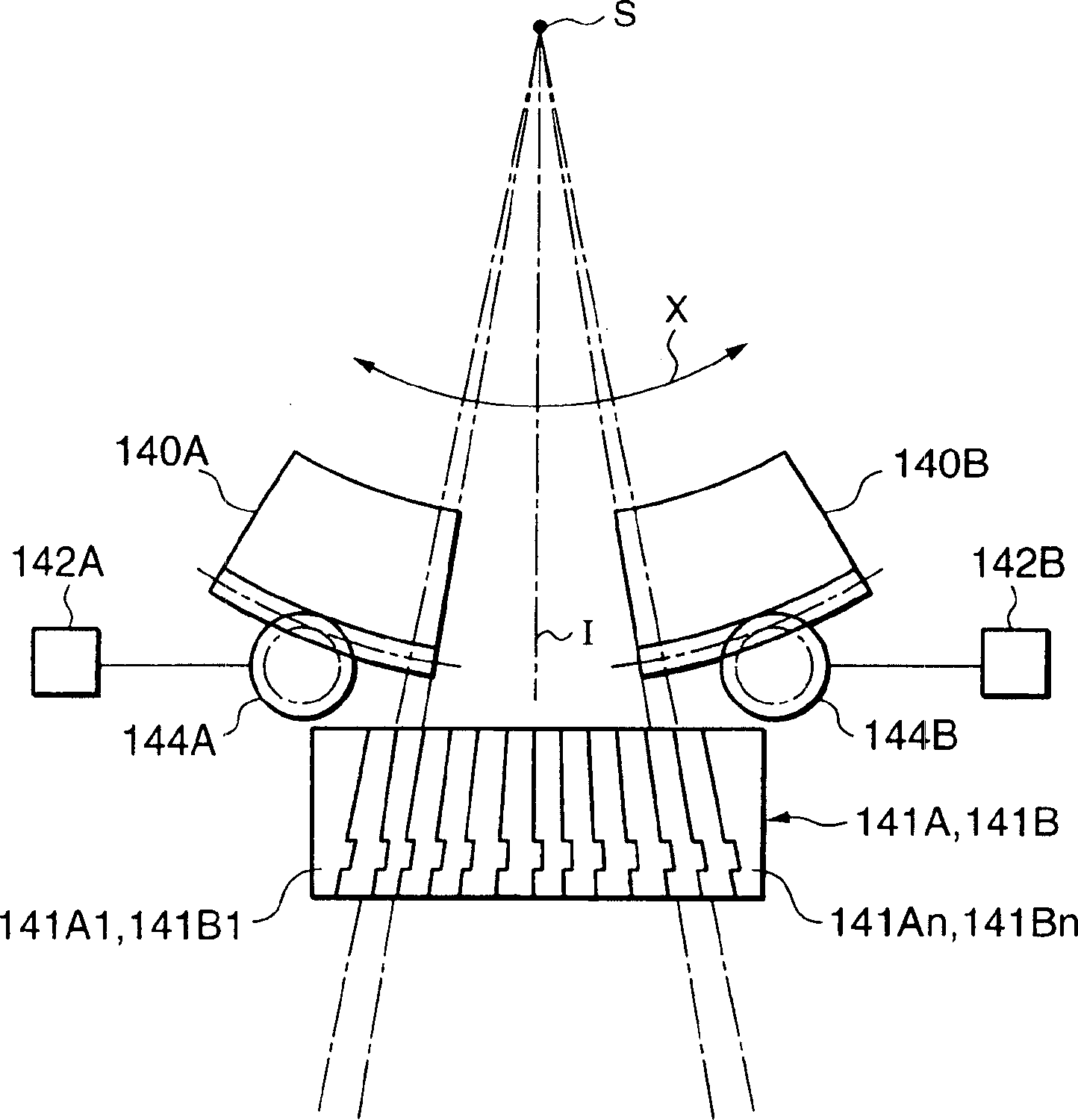
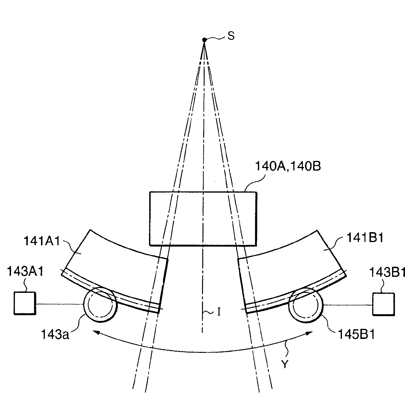
[0073] The first embodiment illustrates collimating blade position detection with a laser beam. In the second example, reference will be made to Figures 14 to 22 Various types of collimation blade position detection using multiple laser beams will be described.
Login to View More PUM
 Abstract
A collimating device for controlling a radiation field of an X-ray radiated from an X-ray radiator. The device includes a plurality of first collimating leaves, a plurality of second collimating leaves, a beam generator, a detector, a memory, and a controller. The plurality of second collimating leaves oppose the first collimating leaves. The beam generator is configured to generate a beam. The beam emanates between the first collimating leaves and the second collimating leaves. The detector is configured to detect the beam. The memory is configured to store position information of each leaf of the first and second collimating leaves when the each leaf is determined to intersect the beam based on the detection. The controller is configured to position the each leaf based on the position information so as to control the radiation field.
Description
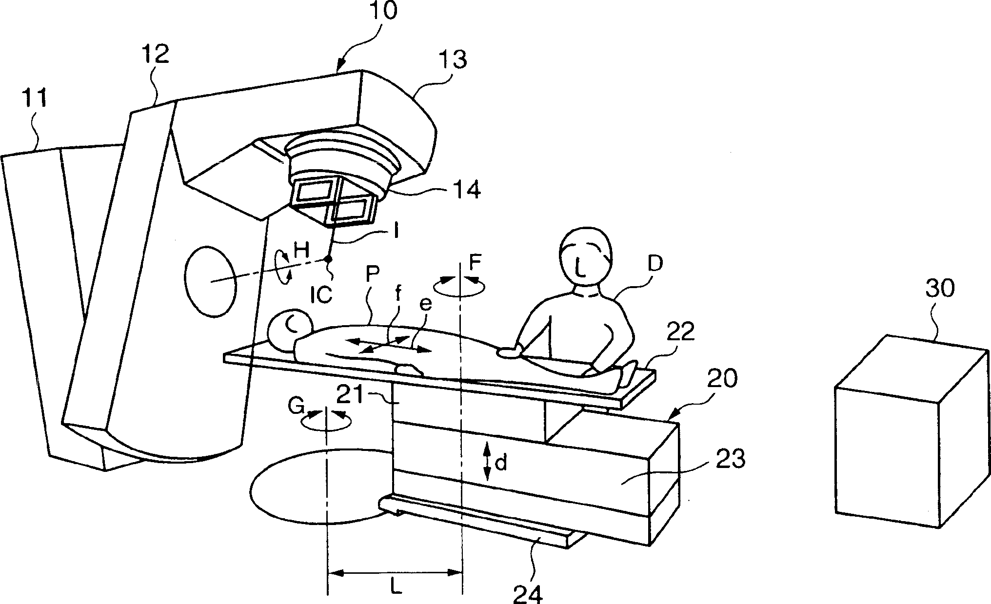
[0001] Cross References to Related Applications [0002] This application is based on and claims priority from prior Japanese Patent Application No. P2003-67559 filed on March 13, 2003, the entire contents of which are hereby incorporated by reference. technical field [0003] The invention relates to a collimator used in a radiotherapy device and controlling an irradiation field through a plurality of collimating blades. The invention also relates to a method of positioning collimating blades of the collimator. Background technique [0004] When using radiotherapy equipment or X-ray diagnostic equipment, it is very important to reduce the amount of X-ray exposure irradiated to a subject such as a human body. A number of techniques have been proposed to achieve a reduction in X-ray exposure, one well known technique is the use of collimators. A collimator reduces the radiation field by reducing the size of its aperture. The aperture size is controlled by adjusting the pos...
Claims
Login to View More Application Information
Patent Timeline
 Patent Type & AuthorityApplications(China)
IPC IPC(8): A61N5/10G21K1/04
CPCA61N5/1042G21K1/046G21K1/04
Inventor野口正
OwnerTOSHIBA MEDICAL SYST CORP