Cryogenic fluid joint

A cryogenic fluid, coupling technology, used in couplings, mounting devices for container construction, gas/liquid distribution and storage, etc.

Inactive Publication Date: 2004-09-29
J C CARTER JAPAN
View PDF1 Cites 3 Cited by
  • Summary
  • Abstract
  • Description
  • Claims
  • Application Information

AI Technical Summary

Problems solved by technology

Therefore, cryogenic fluid couplings can be used alone while addressing both ice and gas emissions

Method used


Image

  • Cryogenic fluid joint
  • Cryogenic fluid joint
  • Cryogenic fluid joint

Examples


Embodiment Construction

[0066] Specific embodiments of the present invention will be described below with reference to the accompanying drawings.

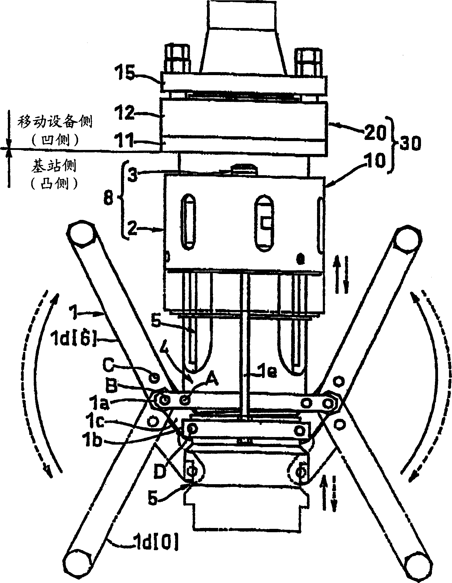
[0067] figure 1 It is a front view of the appearance of the cryogenic fluid coupling according to the present invention.

[0068] The cryogenic fluid coupler 30 includes a male connector 10 provided on a storage tank, such as a storage tank at a base or a storage tank at a liquefied natural gas (LNG) supply station, and a female connector 20 provided at a Mobile equipment, such as tank trailers or tanks on LNG powered vehicles. The cryogenic fluid coupler 30 is used to supply cryogenic fluid such as LNG between the storage tank and the mobile equipment.

[0069] The male connector 10 includes an engaging linkage 1 . The joint link mechanism 1 includes a joint control rod 1d. Engage the control lever 1d and use the lever to carry out the connection operation. The connection operation reaches the lock maintenance state indicated by the solid line [6] a...


PUM


Abstract

Provided is a cryogenic fluid coupling (30) in which coalescence of male (10) and female coupling (20) is maintained even when the cryogenic fluid coupling is used alone while solving ice and gas purging problems, and which has satisfactory workability and a wide scope of application. The cryogenic fluid coupling is used to supply of cryogenic fluid between a storage tank and a mobile unit. A coalescing lock mechanism (8), which maintains or releases the coalescence of the male coupling member (10) and the female coupling member (20) in association with the coalescing linkage mechanism (1), is provided.

Description

technical field [0001] The present invention relates to a cryogenic fluid coupling for supplying a cryogenic fluid, such as liquefied natural gas (LNG), between a storage tank and a tank of a mobile device. Background technique [0002] Generally, a cryogenic liquid such as liquefied natural gas (LNG) is supplied from a storage tank provided, for example, at a base to a tank of a mobile device such as a tank trailer in the following manner. Set an on / off valve on the base and on the mobile unit respectively. The base is provided with a loading arm on a supply line extending from the on / off valve to the mobile device. Its connecting end has a flange structure. The connecting flange can move vertically and horizontally and can reside in any position. The end of the supply pipe of the mobile device also has a flange structure. The connection flange of the base is aligned with the flange of the mobile unit, and the two flanges are bolted together so that the supply pipes of ...

Claims


Application Information

Patent Timeline
Patent Type & Authority Applications(China)
IPC IPC(8): F16L37/12F16L37/36
CPCF17C2205/037F16L37/36F16L37/28
Inventor 约翰·皮克特詹姆士·图尔伊
Owner J C CARTER JAPAN
Why Eureka
Try Eureka