Water supply tank for heat exchanger

A technology for heat exchangers and water tanks, which is applied to heat exchange equipment, indirect heat exchangers, heat exchanger shells, etc., and can solve the problem of not being able to fully ensure the cross-sectional area of ​​the tube 15 channel

Inactive Publication Date: 2004-10-06
CALSONIC KANSEI CORP
View PDF1 Cites 4 Cited by
  • Summary
  • Abstract
  • Description
  • Claims
  • Application Information

AI Technical Summary

Problems solved by technology

On the other hand, in the case where the diameter of the tube 15 is small in order to make the condenser 1 compact, there is a problem that the passage cross-sectional area S of the tube 15 cannot be sufficiently secured.

Method used


Image

  • Water supply tank for heat exchanger
  • Water supply tank for heat exchanger
  • Water supply tank for heat exchanger

Examples


Embodiment Construction

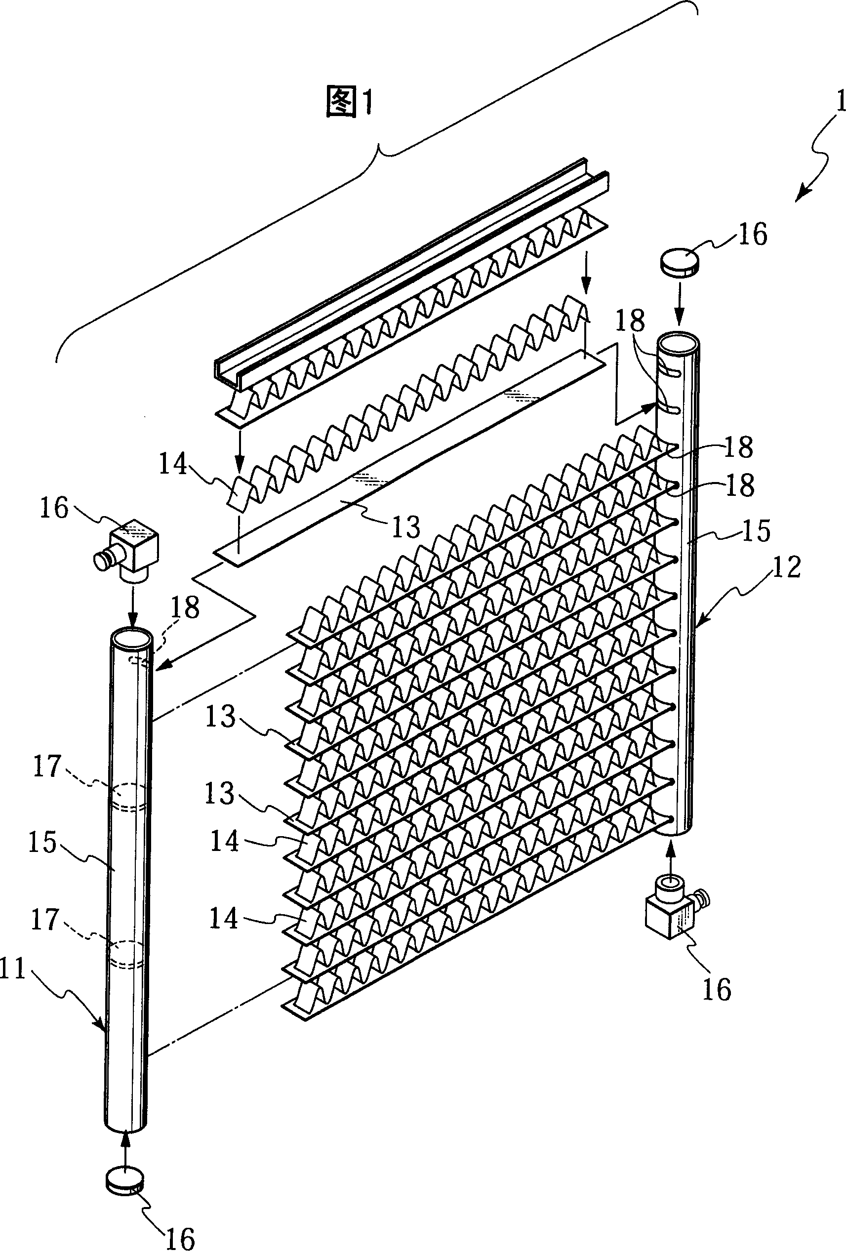
[0031] An embodiment of the present invention will be described with reference to the drawings. In this case, since the entire structure of the heat exchanger is the same as a conventional heat exchanger, description thereof is omitted.

[0032] refer to Figure 5 , according to the present embodiment, the header tank 31 has a pipe 32, a closure member (not shown) that closes the openings at both ends of the pipe 32, and a partition plate (not shown) that separates the channels extending longitudinally in the pipe 32. .

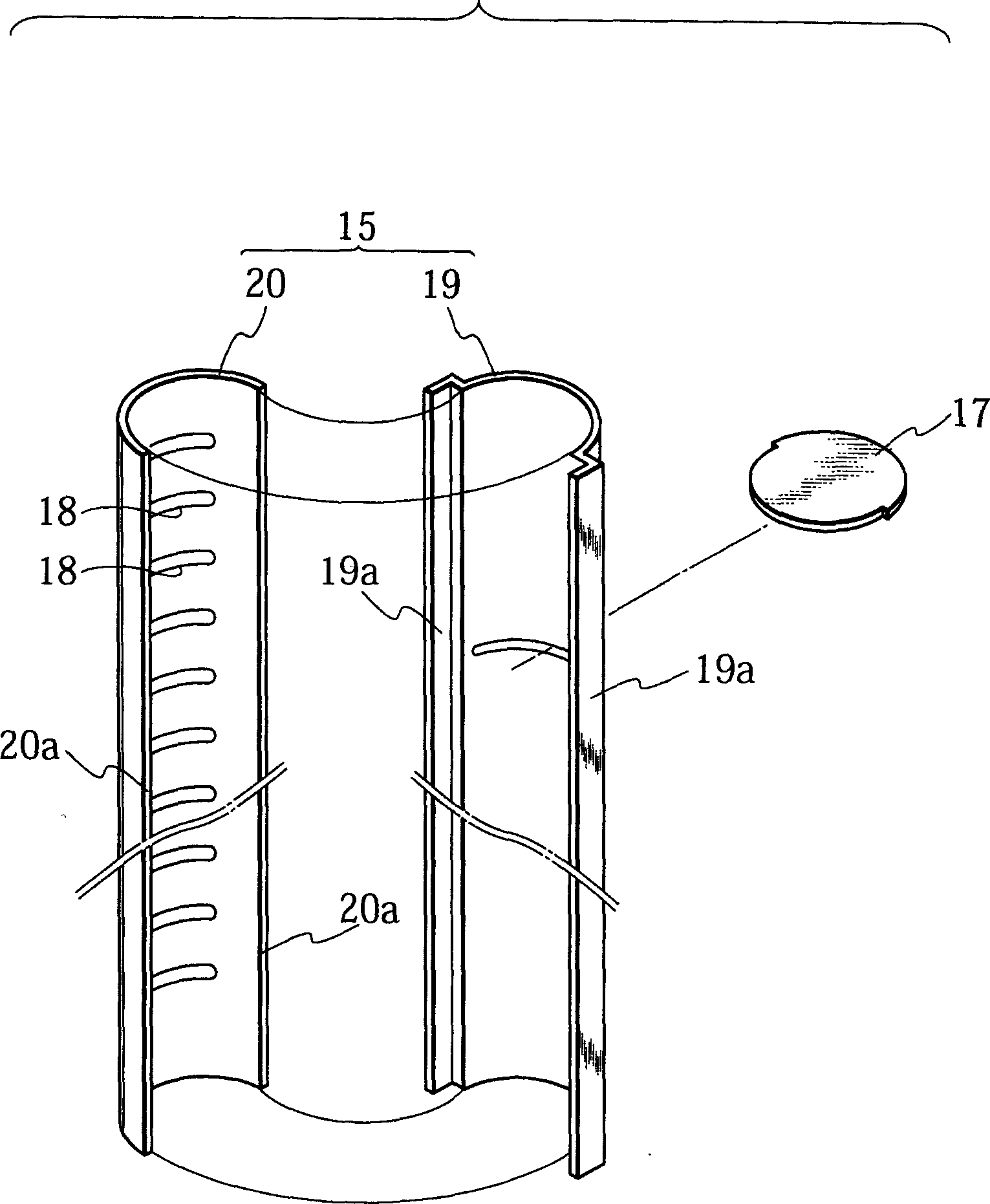
[0033] The tube 32 will be described in detail below. Such as Figures 5 to 7B As shown, the tube 32 is formed into a tubular shape by joining two longitudinally separate bodies 32A and 32B.

[0034] The first independent body is formed in a C-shaped cross-sectional shape while being provided with a tube holding wall portion 34 and a pair of straight portions 36 protruding from both ends of the tube holding wall portion 34 in approximately vertical direct...


PUM


Abstract

A pipe of a header pipe is formed by combining two separated bodies separated along a longitudinal direction. The first separated body has a tube holding wall portion including an insertion hole inserting a flat tube thereto, and a pair of straight portions protruded from the tube holding wall portion in an approximately orthogonal direction and set along both sides in a width direction of the tube, and is formed in a C-shaped cross sectional shape.

Description

technical field [0001] The invention relates to an upper water tank of a heat exchanger such as a condenser applied to an air conditioner such as an automobile. Background technique [0002] Figure 1 and figure 2 A conventional heat exchanger (condenser) used on an air conditioner is shown (Japanese Unexamined Patent Application No. H7-027496). As shown in Figure 1, the condenser 1 consists of a pair of opposite upper water tanks 11 and 12, a plurality of flat tubes 13 arranged between the upper water tanks 11 and 12, and a corrugated heat dissipation tube inserted between the flat tubes 13 and 13. Composition of 14 pieces. [0003] Each header tank 11 and 12 is composed of a pipe 15 , a closure member 16 closing the open portions at both ends of the pipe 15 , and a partition plate 17 for dividing a channel extending longitudinally in the pipe 15 . In this embodiment, the closure 16 doubles as a connection to either the outlet or inlet pipe. [0004] Figure 1 and figure...

Claims


Application Information

Patent Timeline
Patent Type & Authority Applications(China)
IPC IPC(8): B60H1/32F25B39/00F28F1/02F28F9/02F28F9/18
CPCF28F9/0224F28F9/0243Y10T29/4935
Inventor 桧山仁一新滨正刚
Owner CALSONIC KANSEI CORP
Why Eureka
Try Eureka