Eureka AIR delivers breakthrough ideas for toughest innovation challenges, trusted by R&D personnel around the world.

Vertical envelope feeding machine

It is a vertical and set machine technology, which is applied to tires, other household appliances, household appliances, etc. It can solve the problems of easy inclination of the bottom, small contact area, intersection, etc., so as to avoid relative sliding, ensure the cross-sectional area, and avoid cross-short circuits. Effect

Active Publication Date: 2019-12-31
绍兴市雨芸机械有限公司
View PDF15 Cites 0 Cited by
  • Summary
  • Abstract
  • Description
  • Claims
  • Application Information

AI Technical Summary

Problems solved by technology

[0002] The enveloping sleeve, also known as the retreading rubber sleeve, is a special annular rubber sleeve used in the pre-vulcanized retreading method. On the day of use, the tires that have been pasted with pre-vulcanized tires are fully enclosed, and the air in the sleeve is sucked out with a vacuum pump, so that Tighten the stone-covered tire, and then send it into the vulcanization tank to pressurize and vulcanize with hot water. The encapsulation sleeve is made of elastomer material, which has the characteristics of heat resistance, flex resistance and sealing. The existing technology is driven by more than two cylinders. The fixed claws are disassembled and fixed. Because the fixed claws have many bearing changes and a large number, the bottom is prone to tilt and cross. The ends of the second fixed claws are relatively sharp. perforation

Method used


Image

  • Vertical envelope feeding machine
  • Vertical envelope feeding machine
  • Vertical envelope feeding machine

Examples


Embodiment

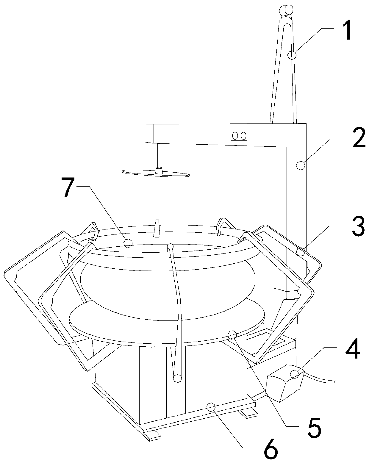
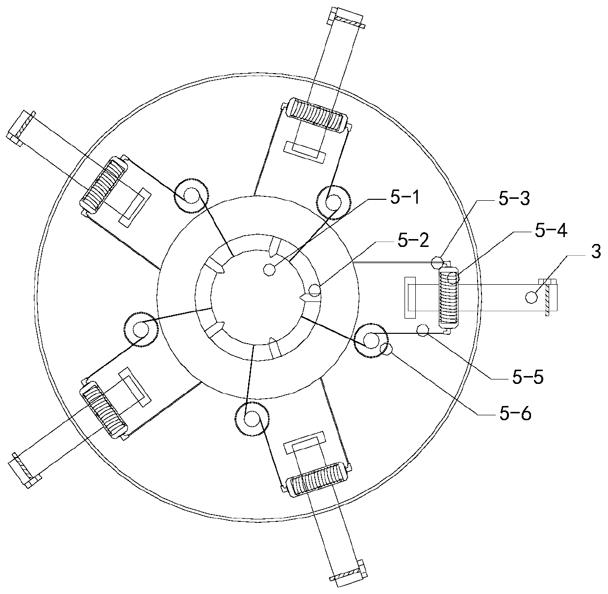
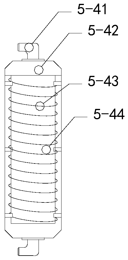
[0030] see Figure 1-Figure 8 , the present invention provides a vertical upper encapsulation machine, the structure of which includes a support column 1, a support shelf 2, a fixed claw 3, an electric control box 4, a repelling structure 5, a base 6, and a contactor 7, and the base 6 is directly above the top More than two fixed claws 3 are installed, and the fixed claws 3 are distributed evenly and equidistantly. A shelf 2 is installed on one side of the base 6, and an electric control box 4 is arranged on the front end of the shelf 2. The electric control box 4 is in movable contact with the shelf 2, the top of the shelf 2 is vertically provided with a support shelf 2, the support shelf 2 and the shelf 2 are welded by a welding machine, and a support column 1 is also installed on the top surface of the support shelf 2, and the fixed A repelling structure 5 is provided near the bottom of the claw 3 near the base 6 , and a contactor 7 is installed at the end of the fixed claw...


PUM


Abstract

The invention discloses a vertical envelope feeding machine. The vertical envelope feeding machine structurally comprises a supporting column, a supporting frame, two or more fixing jaws, an electriccontrol cabinet, a repulsive structure, a base and a contactor. The fixing jaws are mounted at the upper top of the base and are uniformly distributed at equal intervals. The supporting frame is mounted on one side of the base. The electric control cabinet is arranged on the front end face of the supporting frame and movably makes contact with the supporting frame. According to the vertical envelope feeding machine, an electromagnet is arranged at the bottom of each fixing jaw, and the two horizontal ends of each electromagnet are perpendicular to the corresponding fixing jaw, so that the magnetic fields of the electromagnets on every two fixing jaws are repulsive to separating the fixing jaws, and every two fixing jaws are prevented from crossing when used for fixing a tire tread; and theelastic contact area between the contactor and a tire can be automatically adjusted by means of a roller which is arranged on a circular body and can be elastically adjusted through a spring, so thatit is guaranteed that the sectional area is enlarged, the contactor is completely attached and fixed to the tire tread, and fixing is more stable.

Description

technical field [0001] The invention relates to the field of enveloping machines, in particular to a vertical top enveloping machine. Background technique [0002] The enveloping sleeve, also known as the retreading rubber sleeve, is a special annular rubber sleeve used in the pre-vulcanized retreading method. On the day of use, the tires that have been pasted with pre-vulcanized tires are fully enclosed, and the air in the sleeve is sucked out with a vacuum pump, so that Tighten the stone-covered tire, and then send it into the vulcanization tank to pressurize and vulcanize with hot water. The encapsulation sleeve is made of elastomer material, which has the characteristics of heat resistance, flex resistance and sealing. The existing technology is driven by more than two cylinders. The fixed claws are disassembled and fixed. Because the fixed claws have many bearing changes and a large number, the bottom is prone to tilt and cross. The ends of the second fixed claws are re...

Claims


Application Information

Patent Timeline
IPC IPC(8): B29D30/56
CPCB29D30/56
Inventor 陈梅花
Owner 绍兴市雨芸机械有限公司
Why Eureka
Eureka Blog
Learn More