Turbine housing for twin-scroll turbocharger

A technology for turbochargers and turbine housings, applied in the direction of machines/engines, stators, engine components, etc., can solve problems such as engine performance degradation, differences in operating conditions, narrow layout, etc., to suppress flow resistance, prevent performance degradation, The effect of securing the cross-sectional area of ​​the flow path

Active Publication Date: 2015-12-02
MITSUBISHI HEAVY IND ENGINE & TURBOCHARGER LTD
View PDF7 Cites 0 Cited by
  • Summary
  • Abstract
  • Description
  • Claims
  • Application Information

AI Technical Summary

Problems solved by technology

Due to this difference in flow rate, the operating conditions of the engine side upstream of the exhaust gas are differentiated, resulting in a decrease in engine performance
[0015] In addition, in the case of a twin-scroll turbocharger, in order to ensure the cross-sectional area of ​​the vortex flow path, the turbine casing forming the vortex flow path must be enlarged in the radial direction, and there is a problem that it cannot adapt to a narrow layout.

Method used


Image

  • Turbine housing for twin-scroll turbocharger
  • Turbine housing for twin-scroll turbocharger
  • Turbine housing for twin-scroll turbocharger

Examples


Embodiment Construction

[0033] Next, the present invention will be described in detail using the illustrated embodiments. However, the scope of the present invention is not limited to dimensions, materials, shapes, relative arrangements, and the like of components described in the embodiments unless otherwise specified.

[0034] (Embodiment 1)

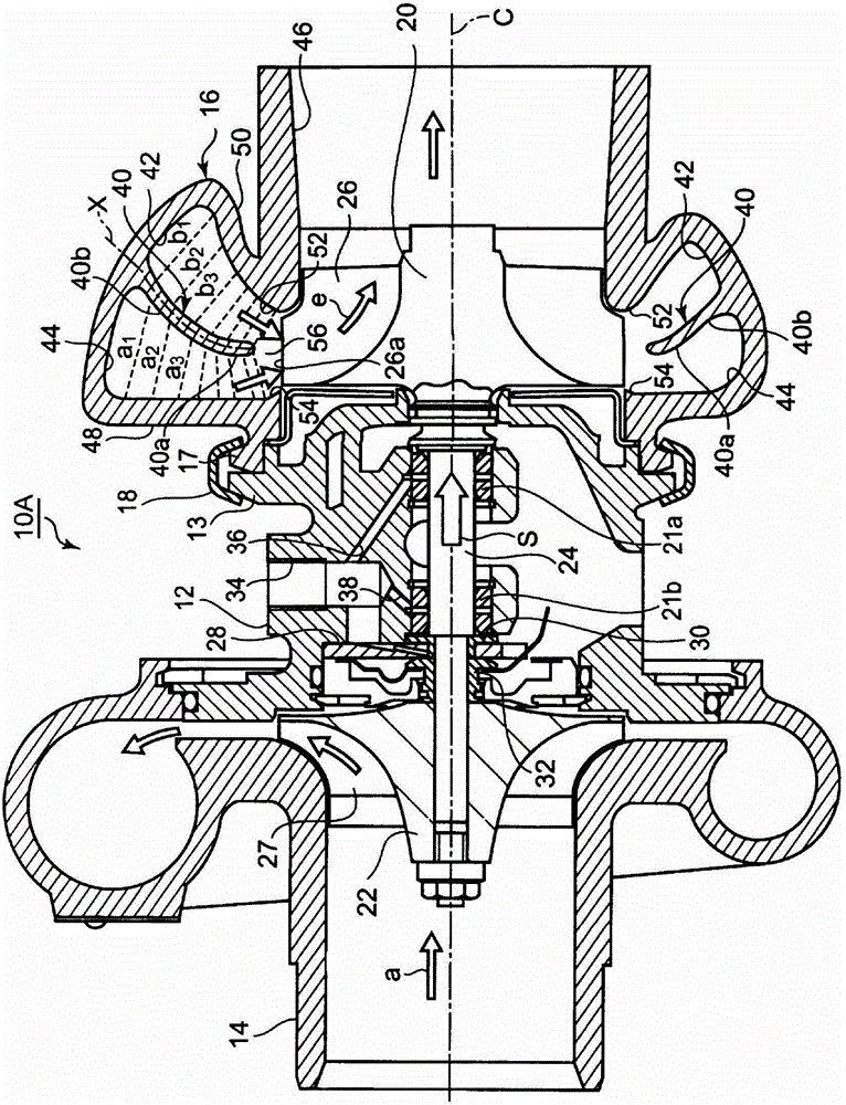
[0035] Now according to figure 1 A first embodiment in which the turbine housing of the present invention is applied to a small twin-scroll turbocharger equipped in a small vehicle such as a car equipped with a multi-cylinder engine will be described. figure 1 In the housing of the illustrated twin scroll turbocharger 10A, a compressor housing 14 and a turbine housing 16 are disposed with a bearing housing 12 interposed therebetween, and these housings on both sides are joined to the bearing housing 12 . The bearing housing 12 and the turbine housing 16 are connected to flanges 13 , 17 at the ends of these housings by means of an annular coupling 18 .

...


PUM


Abstract

In a turbine housing 12 of a turbocharger 10A of a twin-scroll type, a scroll-shaped passage is separated into a front scroll passage 42 and a rear scroll passage 44 by a partition wall 40. A front wall 50 and a root part 40b of the partition wall 40 curve toward a front side to secure cross-sectional areas a1, a2, a3 · · · and b1, b2, b3 · · · . The scroll passages 42, 44 are formed to have equal cross-sectional areas, a tip part 40a of the partition wall 40 is arranged perpendicular to the turbine rotor blade 26 and the scroll passages 42, 44 are symmetrical near the tip part 40a about an axis X so as to eliminate the flow rate difference.

Description

technical field [0001] The present invention relates to a turbine housing of a twin-scroll turbocharger, which suppresses the outer diameter of the housing to be small, and improves the flow state of exhaust gas flowing in two scroll flow paths, thereby suppressing engine performance decline. Background technique [0002] As a turbine casing of a turbocharger equipped on a vehicle or the like, there is known a twin-scroll turbocharger whose flow from the inlet of the turbine casing to the leading edge of the turbine blade is known. The road is divided into the front side (exhaust gas outlet side) and the rear side (bearing housing side) to avoid interference of exhaust gas from a multi-cylinder engine and to effectively utilize exhaust gas pulsation (dynamic pressure) of the engine. In particular, Patent Document 1 and Patent Document 2 disclose such twin-scroll turbochargers. [0003] Now according to image 3 with Figure 4 A structural example of a conventional twin-sc...

Claims


Application Information

Patent Timeline
Patent Type & Authority Patents(China)
IPC IPC(8): F02B39/00
CPCF01D25/24F01D9/026F02B37/025F05D2220/40
Inventor 吉田丰隆惠比寿干
Owner MITSUBISHI HEAVY IND ENGINE & TURBOCHARGER LTD
Why Eureka
Try Eureka