
Liquid distributor in mass transfer column and method of installation and use

A technology of liquid distributor and mass transfer, which is applied in chemical instruments and methods, separation methods, distribution of distillation liquid, etc., and can solve problems such as liquid entrainment

Inactive Publication Date: 2004-10-13
KOCH GLITSCH INC
View PDF1 Cites 6 Cited by
  • Summary
  • Abstract
  • Description
  • Claims
  • Application Information

AI Technical Summary

Problems solved by technology

Because the lower edge of the splash baffle is above and spaced from the upper surface of the underlying mass transfer bed, when the liquid is in the gap between the lower edge of the splash baffle and the upper surface of the mass transfer bed There is still a risk of fluid entrainment during mid-down motion

Method used


Image

  • Liquid distributor in mass transfer column and method of installation and use
  • Liquid distributor in mass transfer column and method of installation and use
  • Liquid distributor in mass transfer column and method of installation and use

Examples


Embodiment Construction

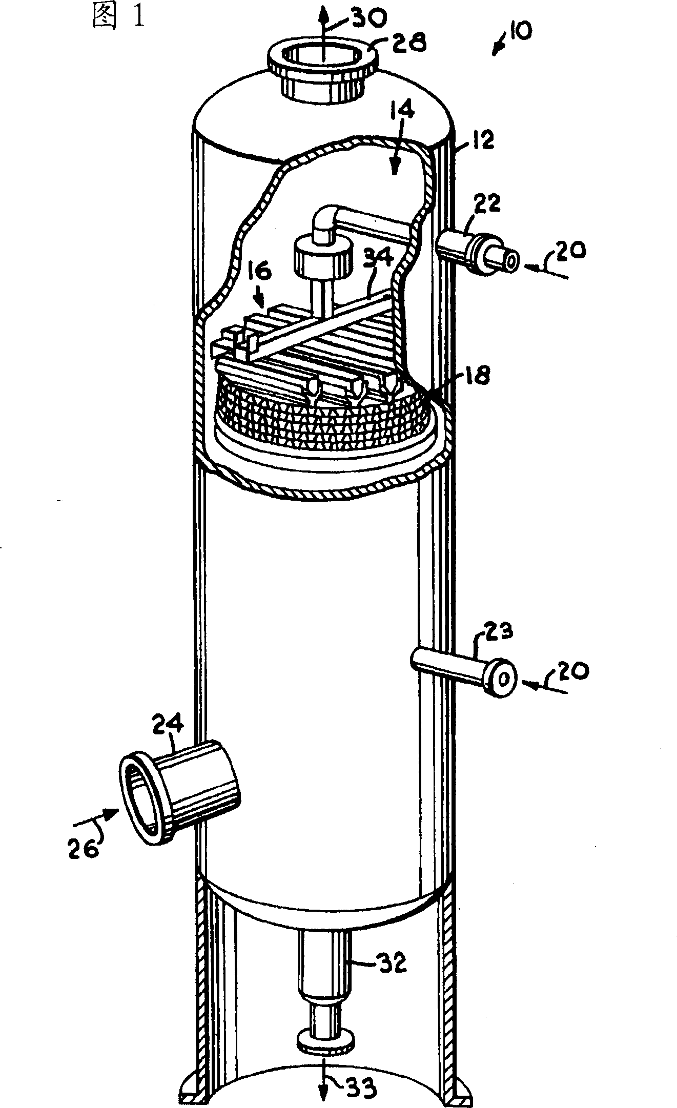
[0015] Referring now in more detail to the drawings, beginning with FIG. 1 , a mass transfer or heat exchange column is generally designated by the reference numeral 10 and includes an upstanding cylindrical shell 12 defining an open interior region 14 in which There are one or more liquid distributors 16 of the present invention and one or more mass transfer beds 18 . Liquid distributor 16 is used to more evenly distribute one or more descending liquid streams across the horizontal section of mass transfer bed 18, which in turn facilitates the separation between the descending liquid stream and one or more ascending vapor streams. s contact. Mass transfer bed 18 includes a variety of known mass transfer devices, including, but not limited to, conventionally known packings, such as structured, grid-like or disordered packings.

[0016] Column 10 is of the type used to process liquid or vapor streams, including those used to obtain fractionated products. Although column 10 is...


PUM


Abstract

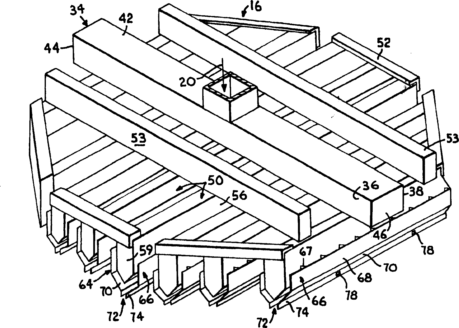
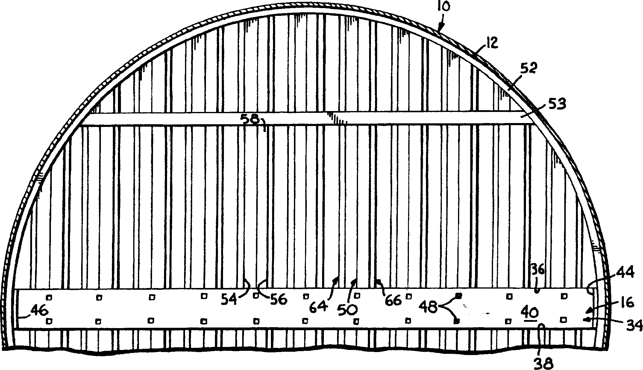
A mass transfer column is provided with a liquid distributor that distributes liquid to an underlying mass transfer bed containing one or more random, grid or structured packing elements. The liquid distributor includes a plurality of elongated troughs that are spaced apart and extend across the column. A plurality of liquid discharge holes are positioned in side walls of the trough and are located in one or more preselected planes that are preferably spaced above a floor of the trough. Splash baffles are spaced outwardly from the trough side walls and include upper portions that are positioned to receive liquid exiting the troughs through the discharge holes. Lower portions of the splash baffles form a constricted discharge outlet in a plane below the trough for delivering liquid from the splash baffles to the underlying mass transfer bed. The liquid discharge holes in one of the trough side walls are offset from those in the other trough side wall to provide a uniform distribution of liquid to the discharge outlet. The splash baffles are vertically adjustable and are intended to be supported on the upper surface of the mass transfer bed so that the discharged liquid is delivered directly to the mass transfer bed, thereby reducing the opportunity for the falling liquid to become entrained in a vapor stream flowing upwardly through teh mass transfer bed. The liquid exiting through the discharge outlet preferably forms a curtain-like flow that blocks or impedes vapor entry upwardly into the discharge outlet. Any vapor that enters the discharge area is able to vent upwardly through the open spacing between the baffles and the associated troughs at a reduced velocity, thereby reducing the opportunity for liquid entrainment. The open spacing also permits any overflow of liquid from the troughs to be captured by the splash baffles for downward flow along the inner faces of the splash baffles.

Description

technical field [0001] The present invention relates generally to a mass transfer column, and more particularly to a liquid distributor for use in such a column and a method of dispensing a liquid using the liquid distributor. Background technique [0002] Uneven liquid distribution leads to poor contact between ascending vapor flow and descending liquid flow and poor mass transfer in the packed portion of the mass transfer column. Typically, trough liquid distributors are used in such columns to receive liquid from the overlying zone and distribute the liquid in a more uniform fashion to the underlying packing bed. These liquid distributors may be open at the top and bottom with a reduced spacing between the bottom side walls so that the liquid funnels down as it exits the distributor as a curtain or sheet of water. Liquid supplied by a dropper type liquid distributor will spread over a structured filling surface and will descend along plate corrugations extending in only ...

Claims


Application Information

Patent Timeline
Patent Type & Authority Applications(China)
IPC IPC(8): B01D3/32B01D3/00B01D53/18
CPCB01D3/008B01J2219/3325B01D53/185B01D3/00B01D3/16
Inventor 克里斯托弗·恩德图利奥·帕特里克
Owner KOCH GLITSCH INC
Learn More