High-precision gear drive pair

A gear transmission, high-precision technology, used in belts/chains/gears, components with teeth, portable lifting devices, etc., can solve the problem of gear transmission backlash, complex structure and assembly, and troublesome precision machining, etc. problems, to achieve the effect of simple structure, reducing vibration and noise, and prolonging service life

Inactive Publication Date: 2012-10-17
TIANJIN QIXING PRECISION MACHINERY
View PDF3 Cites 3 Cited by
  • Summary
  • Abstract
  • Description
  • Claims
  • Application Information

AI Technical Summary

Problems solved by technology

[0004] Existing technology In precision gear transmission, in order to achieve anti-backlash transmission or adjust meshing backlash, commonly used technical solutions include: eccentric bushing adjustment center distance method, double-piece thin gear staggered tooth adjustment method, spring force bias method, double The motor-driven double transmission chain anti-backlash method, the above methods are complicated in structure and assembly, high in cost, only suitable for small power systems, and cannot completely solve the backlash problem of gear transmission
There are also methods such as conical variable tooth thickness gears that adopt radial displacement, such as U.S. Patents US3174356, US3171212 and US5400672. The axial direction is constantly changing, which will directly increase the wear of the gear, and its precision machining is also more troublesome, requiring modification of the machine tool, and poor manufacturability

Method used


Image

  • High-precision gear drive pair
  • High-precision gear drive pair
  • High-precision gear drive pair

Examples


Embodiment Construction

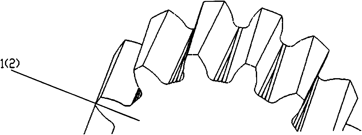
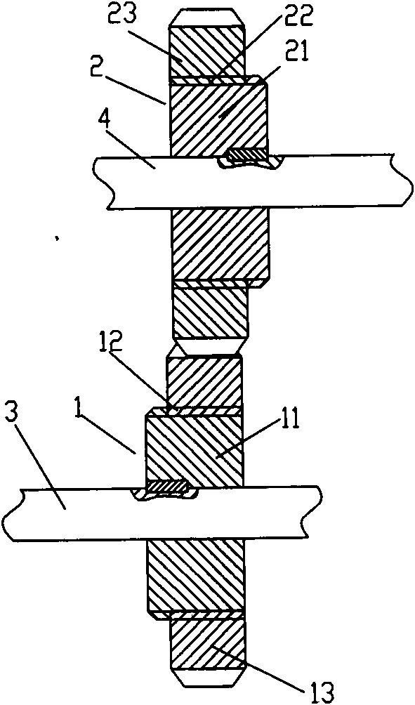
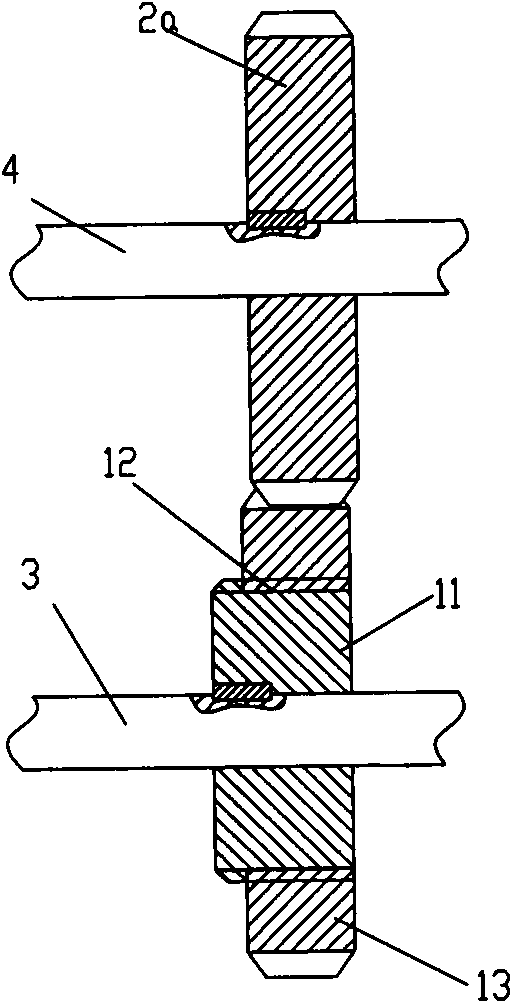
[0017] figure 1 It is the gear tooth shape structure diagram of the present invention, figure 2 It is a schematic diagram of the gear meshing structure (thread transmission) of the present invention, image 3 It is a schematic diagram of the gear meshing structure of the present invention (the second structure of screw transmission). As shown in the figure, the high-precision gear transmission pair of the present invention includes a driving gear 1 and a driven gear 2 meshing with it. The driving gear 2 adopts the form of tangential displacement, and the tangential displacement coefficient changes from small to large along the axial direction to form a gear with variable tooth thickness. The teeth of the driving gear 1 and the teeth of the driven gear 2 The direction of the tangential deformation coefficient of the tooth surface is the same from small to large. As shown in the figure, the tooth thickness of the gear teeth gradually becomes thinner along the axial direction; ...


PUM


Abstract

The invention discloses a high-precision gear drive pair, and is characterized in that a gear adopts gradient tangential deflection, tangential deflection coefficients are changed along an axis direction of a toothed disc from small to large according to a certain rule, so that a certain inclined angle is formed between two teeth surfaces of gear teeth, and an engagement backlash is adjusted through regulating an axial relative position of the mutually engaged gears; a screw thread or cam transmission is adopted, and the axial force generated in the transmission process is utilized, so that two gears are moved timely relatively, the gear backlash and the return difference can be eliminated or reduced, the vibration and the noise are reduced, and the service life is prolonged; in comparison with the other backlash regulating manner in the prior art, the backlash is directly eliminated by utilizing the driving force, and the high-precision gear drive pair has the advantages of simple structure, small volume and the like; by utilizing the radial deflection form, the influence of the tangential deflation on the tooth thickness can be compensated, the intensity of the wheel tooth of the gear is ensured, the contact ratio of engagement is increased, the bearing capacity is high, and the high-precision gear drive pair is suitable for high-speed input in precise transmission.

Description

technical field [0001] The invention relates to a transmission device, in particular to a transmission device with high precision requirements. Background technique [0002] Gear transmission is used to transmit motion and power between two shafts. Compared with other mechanical transmissions, gears have the advantages of compact structure, stable operation, and low noise, so they are widely used in various machines and instruments. [0003] With the development of production technology and the demand for high-quality products, especially the development of precision heavy-duty transmission, higher requirements are put forward for the control of transmission accuracy and backlash. [0004] Existing technology In precision gear transmission, in order to achieve anti-backlash transmission or adjust meshing backlash, commonly used technical solutions include: eccentric bushing adjustment center distance method, double-piece thin gear staggered tooth adjustment method, spring fo...

Claims


Application Information

Patent Timeline
Patent Type & Authority Applications(China)
IPC IPC(8): F16H55/18
Inventor 罗洋
Owner TIANJIN QIXING PRECISION MACHINERY
Why Eureka
Try Eureka