
Step motor-driven grate burniag device of garbage furnace

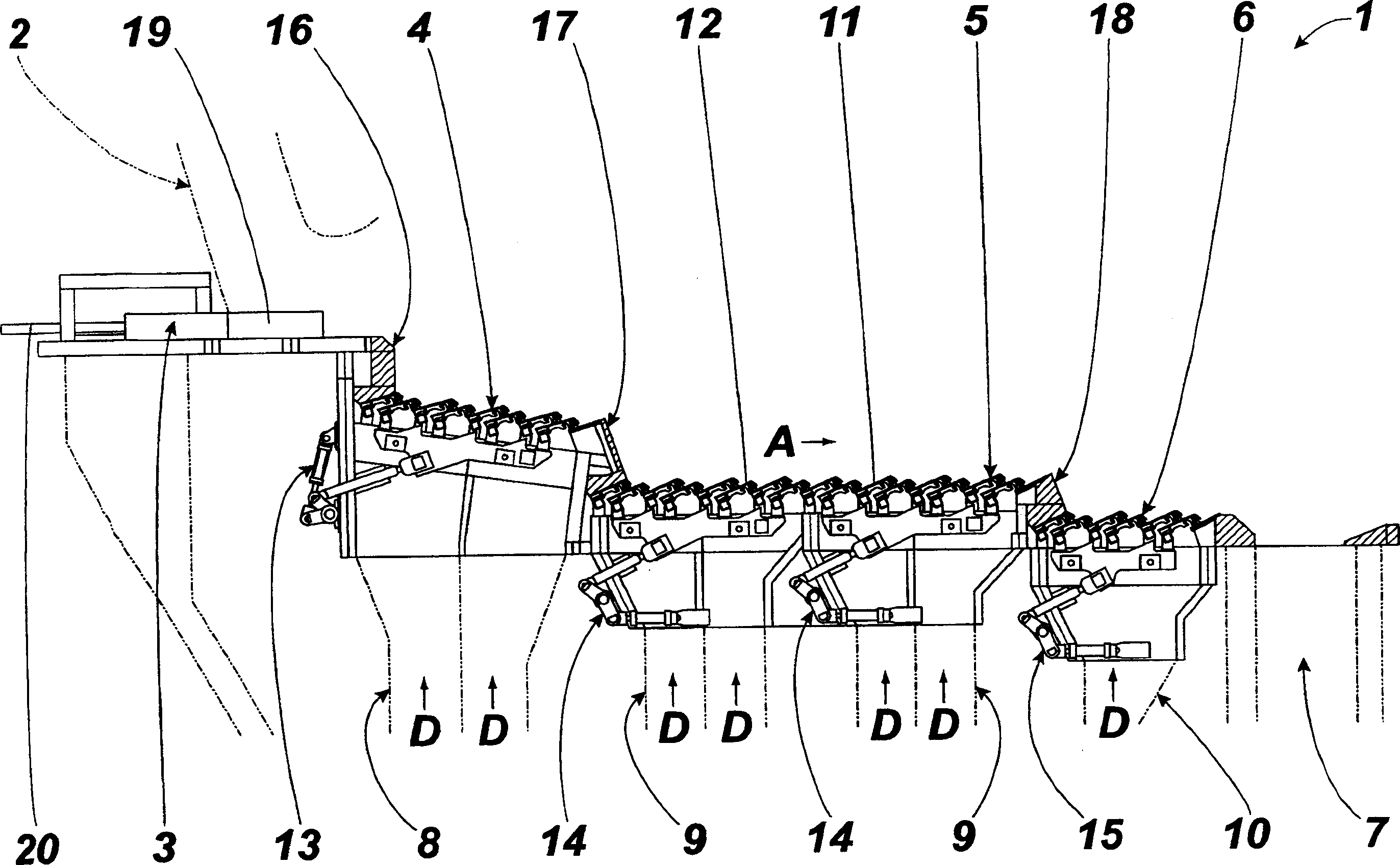
A technology of waste incinerator and motorized grate, which is applied in the direction of incinerator, combustion method, combustion type, etc., and can solve the problem of high overall height of the device

Inactive Publication Date: 2004-10-20
TAKUMA
View PDF1 Cites 8 Cited by
  • Summary
  • Abstract
  • Description
  • Claims
  • Application Information

AI Technical Summary

Problems solved by technology

[0008] However, each motorized grate of this stepped motorized grate combustion device is arranged in a forward-inclining state along the garbage conveying direction, so there is a problem that the overall height of the device is too high

Method used


Image

  • Step motor-driven grate burniag device of garbage furnace
  • Step motor-driven grate burniag device of garbage furnace
  • Step motor-driven grate burniag device of garbage furnace

Examples


Embodiment 2

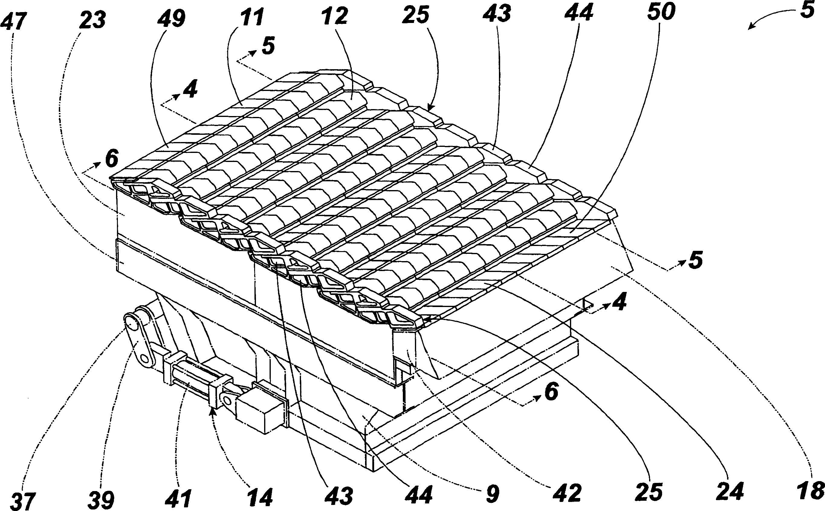
[0099] Embodiment 2 is different from Embodiment 1 except that an air channel 69 is formed on the side plate 25 for air cooling, and the others are the same as Embodiment 1.

[0100] The air passage 69 is formed on the side plate 25 and circulates the cooling air H in the direction opposite to the refuse conveying direction A, while being formed only on the upper portion of the side plate 25 .

[0101] That is, the side plate on the most upstream side ( Figure 14 The fixed grate on the left side is hollow except for the side plate 43), and is provided with a partition wall 70 that separates the hollow part up and down.

[0102] The side plate on the most upstream side ( Figure 14 The fixed fire grate on the leftmost side (side plate 43) in the center is hollow, and an inlet 71 is formed on the front side, and an outlet 72 is formed on the lower side.

[0103] Adjacent front and rear side plates 43 and 44 communicate with adjacent outlets 72 and inlets 71 respectively to fo...


PUM


Abstract

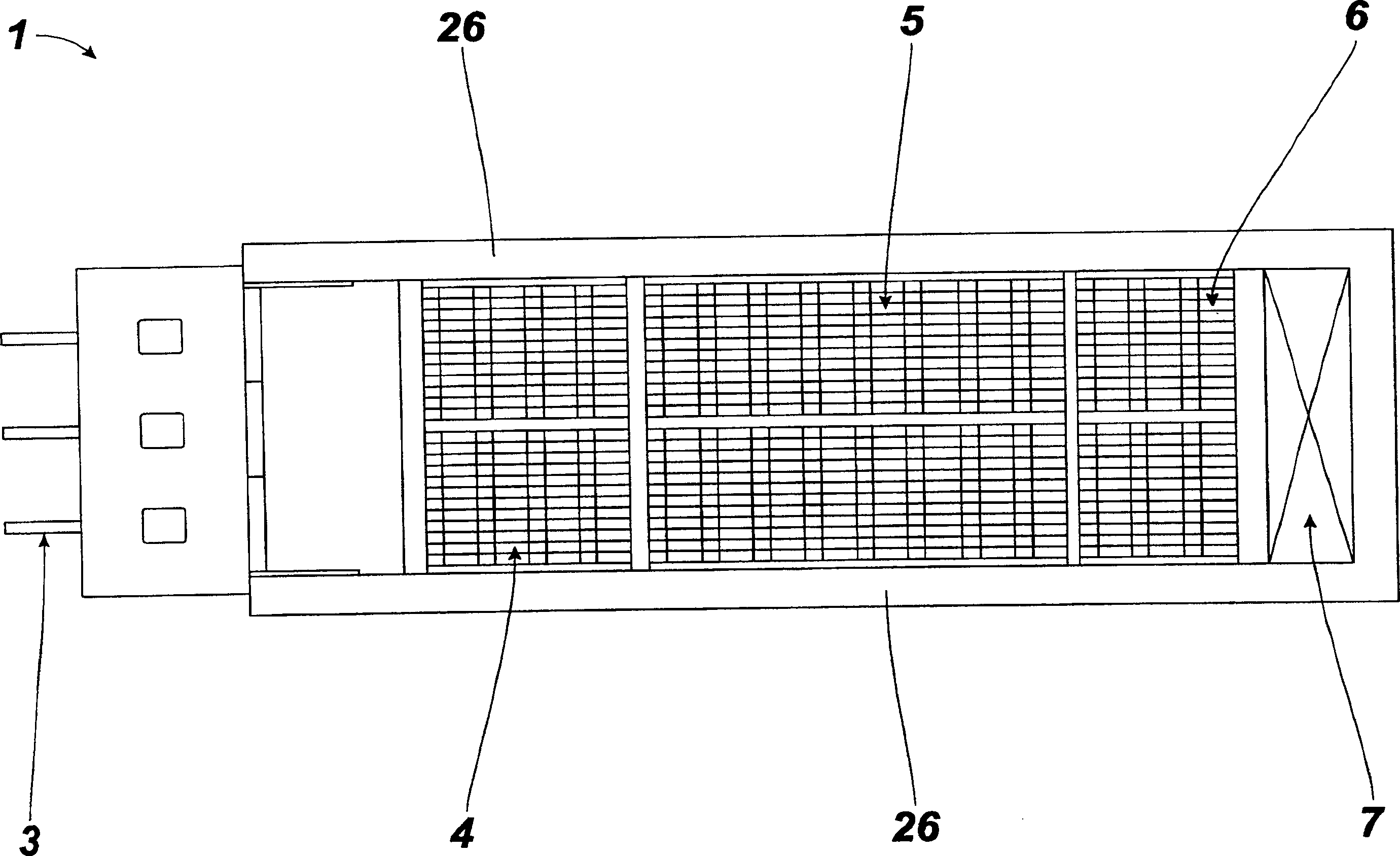
A burner with stepped moving grate for garbage incinerator features that the drying grate, combustion grate and post-combustion grate are arranged in a row with step between adjacent grates, the feed hoppers sunder the grates are used to supply the primary burning air upward to the garbage on grates for continuously burning, and all the grates are driven respectively by the drivers for moving them.

Description

technical field [0001] The present invention relates to improvements in stepped motorized grate burners for incinerators such as municipal waste. Background technique [0002] Usually, the step-type motorized grate combustion device used in the garbage incinerator is successively equipped with a dust feeding device for conveying garbage according to a predetermined amount; a drying motorized grate for drying garbage; a combustion motorized grate for burning garbage; The post-combustion motorized grate of the post-combustion (secondary combustion) garbage, etc., through the hopper arranged under each motorized grate, the primary combustion air is conveyed from the bottom to the garbage on each motorized grate, so that the garbage is conveyed continuously burning. [0003] Moreover, the drying motor grate, the combustion motor grate, and the post-combustion motor grate have approximately the same structure. As these so-called step-type motor grates, there are known ones such ...

Claims


Application Information

Patent Timeline
Patent Type & Authority Applications(China)
IPC IPC(8): F23G5/02F23G5/26
Inventor 西垣正秀日尾英明柴田清筱原武和田哲昌
Owner TAKUMA
Learn More