
Barbecue rack of microwave oven

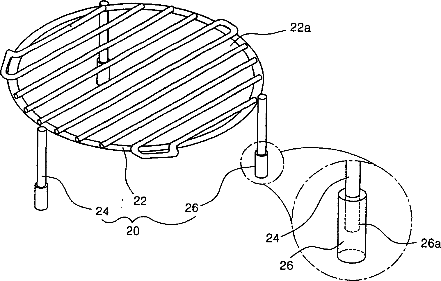
A technology for grills and microwave ovens, which is applied in the invention field of microwave oven grills, and can solve problems such as the detachment of the rubber sleeve bracket 24 and the pressure rise of the insertion hole 26a, and achieve the effect of avoiding the rise of air pressure and preventing detachment

Inactive Publication Date: 2004-10-27
LG ELECTRONICS (TIANJIN) APPLIANCES CO LTD
View PDF0 Cites 2 Cited by
  • Summary
  • Abstract
  • Description
  • Claims
  • Application Information

AI Technical Summary

Problems solved by technology

Therefore, the expansion of the air inside the insertion hole 26a will cause the pressure inside the insertion hole 26a to rise, and the rubber sleeve 26 may be separated from the bracket 24.

Method used


Image

  • Barbecue rack of microwave oven
  • Barbecue rack of microwave oven
  • Barbecue rack of microwave oven

Examples


Embodiment Construction

[0023] The microwave oven grill of the present invention will be described in detail below with reference to the accompanying drawings and embodiments.

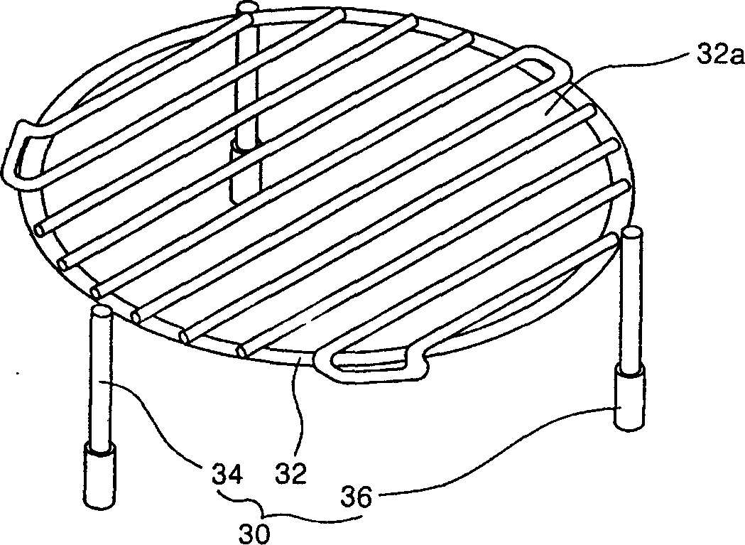
[0024] image 3 It is a three-dimensional view of the structure of the microwave oven grill of the present invention. Figure 4 for image 3 The structural sectional view of embodiment. Such as image 3 , Figure 4 As shown, the microwave oven usually has a grill 30 for grilling fish and meat.

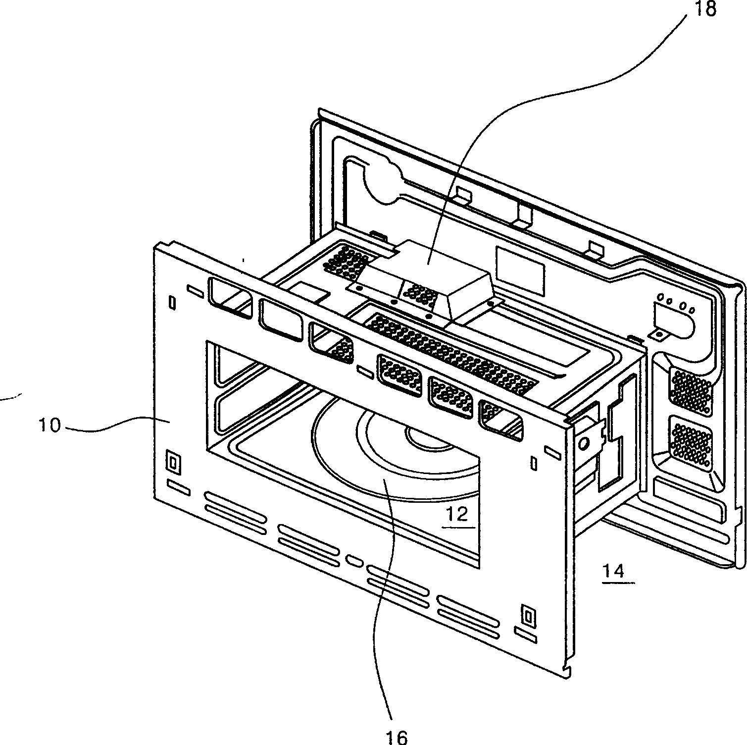
[0025] Usually, the food that needs grilling is placed on grill 30, and grill 30 is placed on tray 16 (please refer to figure 1 ) for cooking. When the tray 16 is rotated, the food is heated by microwave or electric resistance heat.

[0026] In addition, the grill 30 is composed of a grill plate 32 , several brackets 34 , and rubber sleeves 36 . Wherein, food is placed on the top of the grill plate 32 . The bracket 34 supports the grill plate 32 . The rubber sleeve 36 supports the grill 30 above the tray 16 .

[0027] The g...


PUM


Abstract

A roasting frame for microwave oven is composed of a roasting grate, multiple supporting legs, and rubber sleeves with air orifice for sleeving on the lower end of legs. Said air orifice can release the hot air, so protecting rubber sleeve.

Description

technical field [0001] The present invention is an invention related to a microwave oven, in particular an invention related to a microwave oven grill. Background technique [0002] Microwave ovens are cooking appliances that use microwaves and resistance heat to heat food. The original microwave oven just guided the microwave into the grill cavity to heat the food. But in addition to utilizing microwaves to heat food, recent microwave ovens have also introduced electric heater heating. [0003] Such as figure 1 As shown, a grill cavity 12 is formed inside the shell assembly 10 . The grill cavity 12 can utilize microwave or resistance heat to heat food. One side of the housing assembly 10 is provided with an electric control room 14 . Various electronic devices such as magnetrons and high-voltage transformers are arranged in the electric control room 14 . [0004] In addition, a tray 16 is rotatably provided at the center of the bottom surface of the grill chamber 12 ....

Claims


Application Information

Patent Timeline
Patent Type & Authority Applications(China)
IPC IPC(8): F24C7/02F24C15/16
Inventor 李泰勳
Owner LG ELECTRONICS (TIANJIN) APPLIANCES CO LTD
Learn More