
The method of changing the right angle of the top of the groove with a larger size into a clearly rounded corner

A grooved, right-angle technology, applied in the field of changing the right angle at the top of a larger-sized groove into an obvious rounded corner, to prevent sealing, expand the scope of application, and reduce difficulty

Active Publication Date: 2011-12-14
SHANGHAI HUAHONG GRACE SEMICON MFG CORP
View PDF0 Cites 0 Cited by
  • Summary
  • Abstract
  • Description
  • Claims
  • Application Information

AI Technical Summary

Problems solved by technology

[0004] The technical problem to be solved by the present invention is to provide a method for changing the right angle at the top of a larger groove into an obvious rounded corner, which solves the problem of modifying the right angle at the top of the groove into an obvious rounded corner with a small curvature

Method used


Image

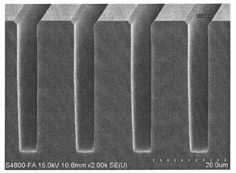
  • The method of changing the right angle of the top of the groove with a larger size into a clearly rounded corner
  • The method of changing the right angle of the top of the groove with a larger size into a clearly rounded corner
  • The method of changing the right angle of the top of the groove with a larger size into a clearly rounded corner

Examples


Embodiment 1

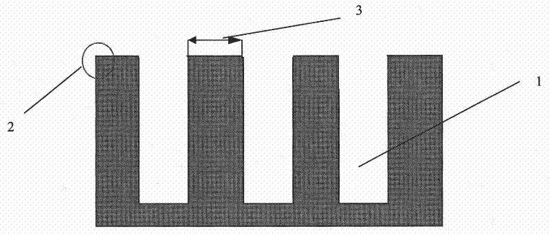
[0025] 1) A series of grooves 1 are etched on the silicon substrate, the width of the groove 1 is 2.0um, the depth of the groove 1 is 10.0um, and the distance 3 between the two grooves is between 0.5um-1.0um, forming Groove top right angle 2 (see figure 2 );

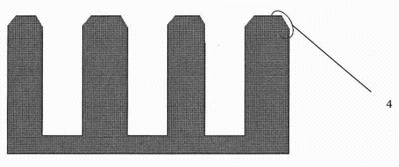
[0026] 2) Use hydrogen chloride gas to etch the right angle 2 on the top of the trench in an atmospheric pressure CVD machine to form an obtuse angle 4 (see image 3 );

[0027] 3) A layer of silicon oxide is grown inside and on the surface of the trench 1 by a thermal oxidation process, with a thickness of 5000 angstroms; and then the silicon oxide is removed with a hydrofluoric acid solution to form a smooth rounded corner 6 at the top of the trench (see Figure 5 ).

Embodiment 2

[0029] 1) A series of grooves 1 are etched on the silicon substrate, the width of the groove 1 is 5.0um, the depth of the groove 1 is 30.0um, and the distance 3 between the two grooves is between 2.0um-10.0um (see figure 2 );

[0030] 2) Use hydrogen chloride gas to etch the right angle 2 on the top of the trench in an atmospheric pressure CVD growth machine to form an obtuse angle 4 (see image 3 );

[0031] 3) Use argon gas to bombard the obtuse angle 4 on the top of the trench in a high-density plasma CVD growth machine to form a relatively rough fillet 5 (see Figure 4 );

[0032] 4) A layer of silicon oxide is grown inside and on the surface of the trench 1 by a thermal oxidation process, with a thickness of 5000 angstroms; and then the silicon oxide is removed with a hydrofluoric acid solution to form a smooth rounded corner 6 at the top of the trench (see Figure 5 ).


PUM


Abstract

The invention discloses a method for changing the right angle at the top of a large-sized trench into an obvious rounded corner, which comprises the following steps: 1) etching a series of trenches on a silicon substrate or a silicon epitaxial layer; 2) using hydrogen halide The gas re-etches the right angle on the top of the groove to form an obtuse angle; 3) A layer of thermal silicon oxide is grown inside and on the surface of the groove in the high-temperature furnace tube; 4) The thermal silicon oxide is removed by wet etching to form a groove Rounded top. The present invention can change the right angle at the top of the larger-sized trench into an obvious rounded corner with a longer arc, thereby avoiding the breakdown of the sharp corner at the top of the trench (such as shallow trench isolation), and reducing the electric field intensity at the tip to improve the performance of the device. The breakdown voltage can also prevent the trench filler from sealing the trench prematurely, thereby reducing the difficulty of trench filling.

Description

technical field [0001] The invention relates to a semiconductor manufacturing process method, in particular to a method for changing the right angle at the top of a large-sized groove into an obvious rounded angle. Background technique [0002] The trench structure is a common structure in the semiconductor manufacturing process, and its functions include isolation, conduction connection (between two layers of metal), depletion, etc. In some cases, in order to avoid breakdown at the sharp corner of the trench top (such as shallow trench isolation), the electric field strength at the tip is reduced to increase the breakdown voltage of the device, or in order to reduce the difficulty of trench filling (sharp trench isolation). The growth angle is 270°, while the growth angle of the smooth surface is 180°, which reduces the growth rate of the top), to prevent the groove filler from sealing the groove prematurely, it is necessary to treat the groove top at right angles, a common...

Claims


Application Information

Patent Timeline
Patent Type & Authority Patents(China)
IPC IPC(8): H01L21/306H01L21/311H01L21/3065H01L21/762
Inventor 刘继全
Owner SHANGHAI HUAHONG GRACE SEMICON MFG CORP
Learn More