
Method and device for utilizing giant magnetic resistance read head for correcting read error in correction disc drive

A disk drive and read error technology, applied in the field of read errors, can solve problems such as breakdown of GMR read elements

Inactive Publication Date: 2004-10-27
KK TOSHIBA
View PDF3 Cites 4 Cited by
  • Summary
  • Abstract
  • Description
  • Claims
  • Application Information

AI Technical Summary

Problems solved by technology

[0012] However, with the prior art method described above, when performing a pinning reset to correct the magnetization direction of the pinned layer, the GMR read element may physically break down if a current pulse is used as the reset pulse
Also, even if a bias current with a supply current value excessively larger than the standard value is used, the method of using both bias current and write current may cause the same problem

Method used


Image

  • Method and device for utilizing giant magnetic resistance read head for correcting read error in correction disc drive
  • Method and device for utilizing giant magnetic resistance read head for correcting read error in correction disc drive
  • Method and device for utilizing giant magnetic resistance read head for correcting read error in correction disc drive

Examples


Embodiment Construction

[0023] Embodiments of the present invention will be described below with reference to the accompanying drawings.

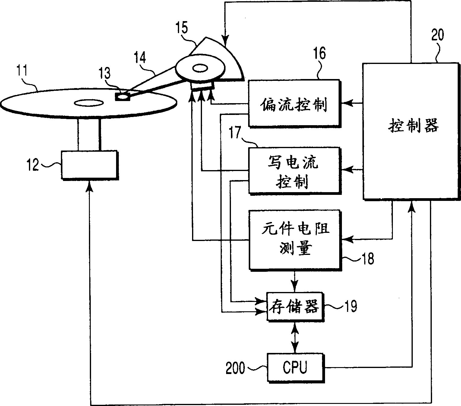
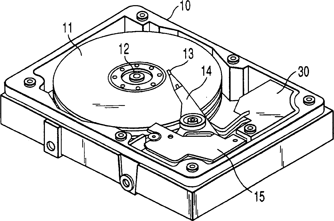
[0024] figure 1 is a view showing an essential part of the disk drive according to the present embodiment. figure 2 is a view showing the appearance of the disk drive.

[0025] (Construction of Disk Drive)

[0026] The disk drive includes a housing 10 accommodating a disk medium 11, a spindle motor (SPM) 12, a magnetic head 13, an actuator 14, and a circuit board 30 on which various circuits are mounted, such as figure 2 shown.

[0027] like figure 1 As shown, the disk medium 11 is rotated by the SPM 12 . The head 13 is mounted on the actuator 14 so that the driving force of the voice coil motor causes the head 13 to move radially on the disk medium 11 . The head 13 is a magnetic head in which a GMR read element (GMR sensor) and a write element are respectively mounted on the same slider.

[0028] The disk drive also has, for example, a bias current contr...


PUM


Abstract

Method and apparatus for read error recovery in a disk drive with a GMR read head. A disk drive is disclosed which has a facility to perform a pinning reset operation on a GMR read element included in a head (13) if a read retry operation fails to achieve recovery from a read error. When a bias and write currents are supplied to the head (13), a CPU 200 of the disk drive determines an optimum bias and write currents on the basis of a temperature measured value of the GMR read element.

Description

technical field [0001] The present invention relates generally to disk drives, and more particularly to correcting read errors during read operations using a GMR read head. Background technique [0002] In recent years, a disk drive typified by a hard disk drive utilizes a magnetic head having a giant magnetoresistance (GMR) read element (also called a GMR sensor) and a write element respectively provided on the same slider, thus facilitating high-density recording . [0003] The GMR read element operates as a read head to read data recorded on the disk media. The write element operates as a write head to generate a recording magnetic field according to a write current to magnetically record data on a disk medium. [0004] A GMR read element is usually designed with two ferromagnetic layers passing through a nonmagnetic layer. One of the ferromagnetic layers is called the free layer and it is magnetized into a fixed orientation in the absence of an external magnetic field...

Claims


Application Information

Patent Timeline
Patent Type & Authority Applications(China)
IPC IPC(8): G11B5/09G11B5/00G11B5/012G11B5/02G11B5/39G11B5/40G11B5/455G11B5/465G11B19/04G11B20/18G11B27/36
CPCG11B5/012G11B19/04G11B5/3903G11B5/40G11B2005/0008G11B5/465G11B2005/001G11B27/36G11B2220/20G11B2005/0018G11B2020/183G11B2005/0016
Inventor 中洋之
Owner KK TOSHIBA
Learn More