Body-building equipment of remotely controlled weight-matching and methods of use
A technology for fitness equipment and mechanism selection, which is applied to gymnastic equipment, muscle training equipment, heavy objects, etc. It can solve problems such as troublesome operation, time-consuming, and changing the selection of counterweights, and achieves convenient operation, space saving, and miniaturization The effect of the design
- Summary
- Abstract
- Description
- Claims
- Application Information
AI Technical Summary
Problems solved by technology
Method used
Image
Examples
Embodiment 1
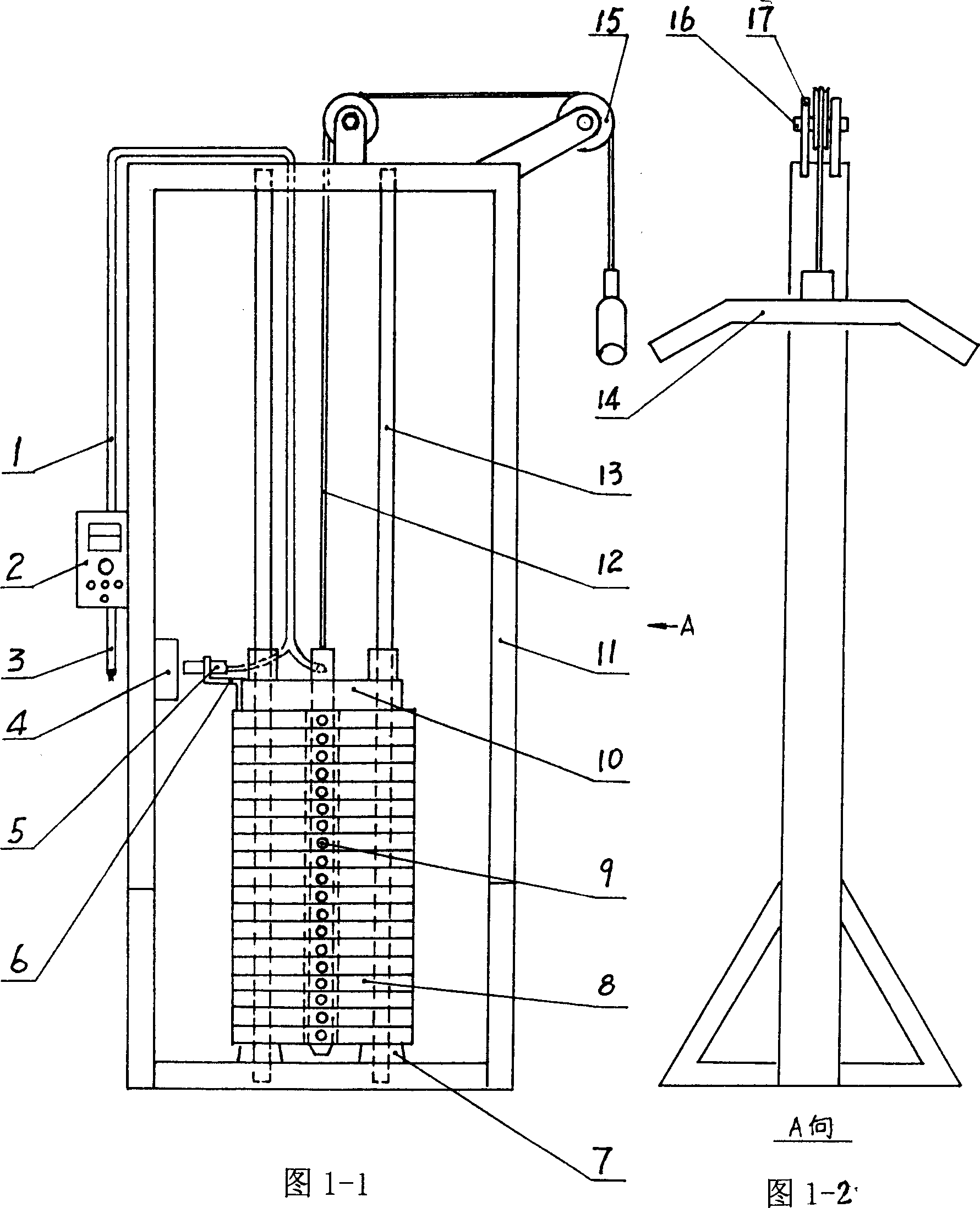
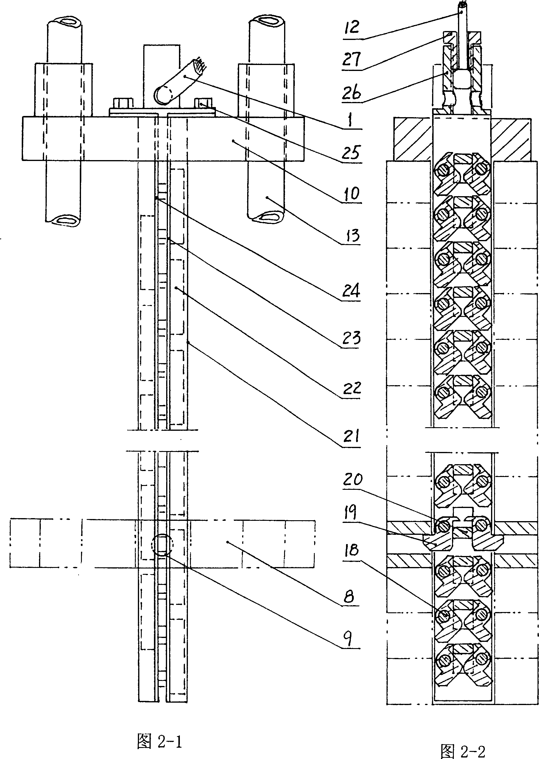
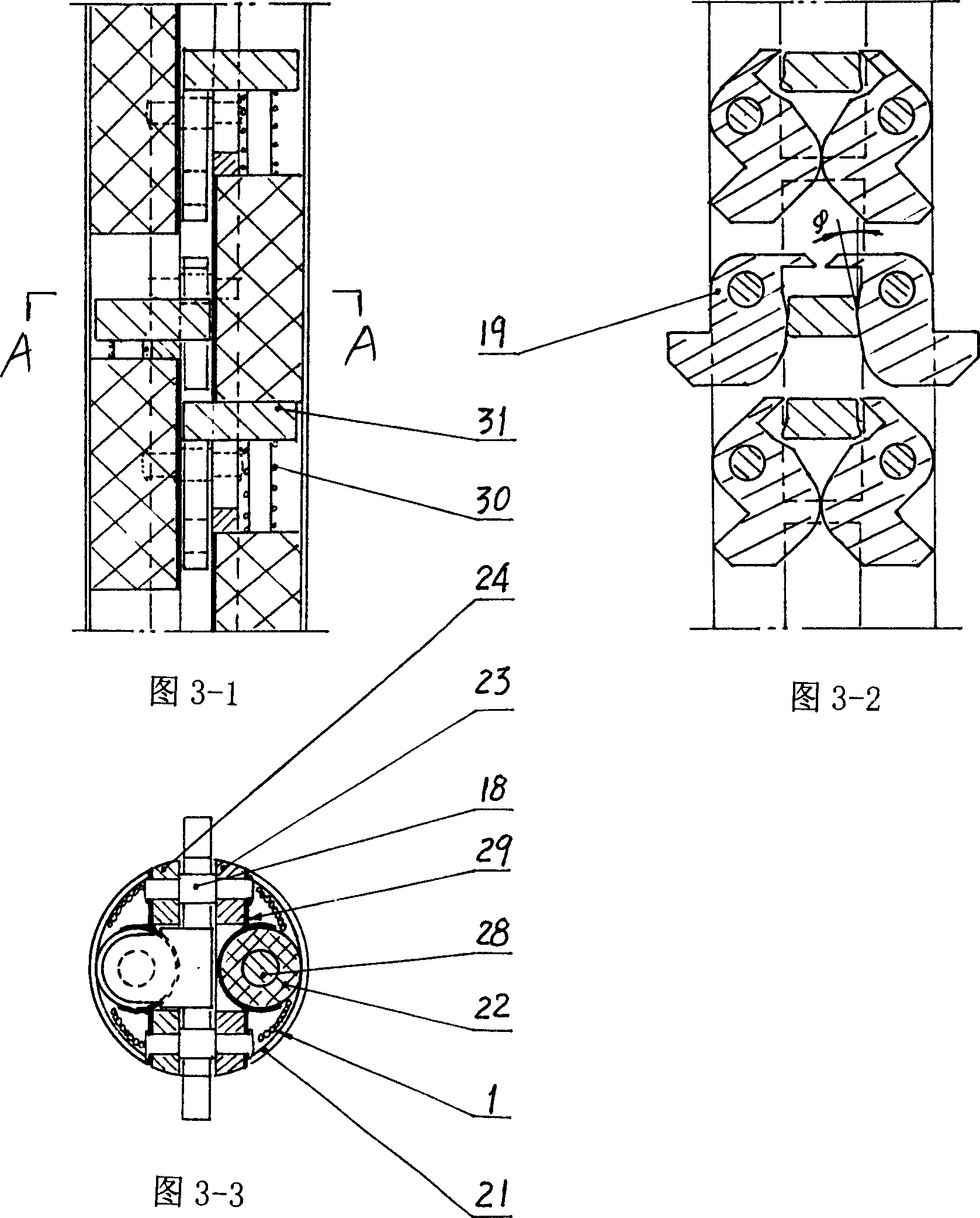
[0050] Example 1, as shown in Figure 1-1 to Figure 4 As shown, the fitness equipment adopting the remote control selection weight mechanism of the present invention is mainly composed of a frame, a weight mechanism, an action part, a selection mechanism, an operation part and an auxiliary part. in:
[0051] The frame 11 forms the main body structure of the fitness equipment and plays the role of supporting other mechanisms.
[0052] The counterweight mechanism mainly includes a buffer pad 7, an optional iron 8, an optional hole 9 (located on the optional iron 8), a counterweight iron 10, and a conduit 13.
[0053] The action section refers to the long handle 14, which can change the action direction and angle according to the different training parts of the human body, and can exercise muscles such as the chest, back, abdomen, waist, and legs.
[0054] Auxiliary part mainly includes steel cable 12, pulley 15, bearing pin 16, pulley frame 17.
[0055] The operation part main...
Embodiment 2
[0074] Example 2, as shown in Figure 5-1 and Figure 5-2:
[0075] The difference from Embodiment 1 is that the positioning hooks 19 are located on both sides of the outer sides of the oppositely disposed selection irons 8 .
[0076] Left support iron 33 and right support iron 34 are fixedly connected with counterweight iron 10 by screw 32.
[0077] Multiple groups of electromagnets 22 are fixedly connected to the left and right support irons by screws 36 along the vertical direction through the outer skeleton 35 respectively.
[0078] Multiple groups of positioning hooks 19 are respectively riveted and fixed in the grooves of the left and right supporting irons by a plurality of rivets 18 .
[0079] When a certain group of electromagnets 22 was energized, the slide block 31 was pulled by the iron core 28 to move downwards in the vertical direction, so that the positioning hooks 19 of the corresponding group stretched into and hooked the selection holes 9 of the corresponding ...
Embodiment 3
[0083] Example 3, such as Figure 6 Shown:
[0084] A plurality of electromagnets 39 are respectively fixedly connected to the support iron 33 through the disc-shaped frame 38 and a plurality of screws 32 .
[0085] When energized, the iron core 41 is attracted to the right displacement (as Figure 6 In the right side direction), the iron core 41 extends into the selection hole 9 of the corresponding selection iron 8, thereby completing the positioning and selection of the selection iron 8.
PUM
 Abstract
Description
Claims
Application Information
 - R&D
- Intellectual Property
- Life Sciences
- Materials
- Tech Scout
- Unparalleled Data Quality
- Higher Quality Content
- 60% Fewer Hallucinations
Browse by: Latest US Patents, China's latest patents, Technical Efficacy Thesaurus, Application Domain, Technology Topic, Popular Technical Reports.
© 2025 PatSnap. All rights reserved.Legal|Privacy policy|Modern Slavery Act Transparency Statement|Sitemap|About US| Contact US: help@patsnap.com


