Multifunctional body-building equipment and operation guide
A fitness equipment, multi-functional technology, applied in gymnastics equipment, muscle training equipment, heavy objects, etc., can solve the problems of exhaustion, bruising, and failure to reset the counterweight mechanism, etc., to save investment, easy to use, and save repetition The effect of purchase
- Summary
- Abstract
- Description
- Claims
- Application Information
AI Technical Summary
Problems solved by technology
Method used
Image
Examples
Embodiment 1
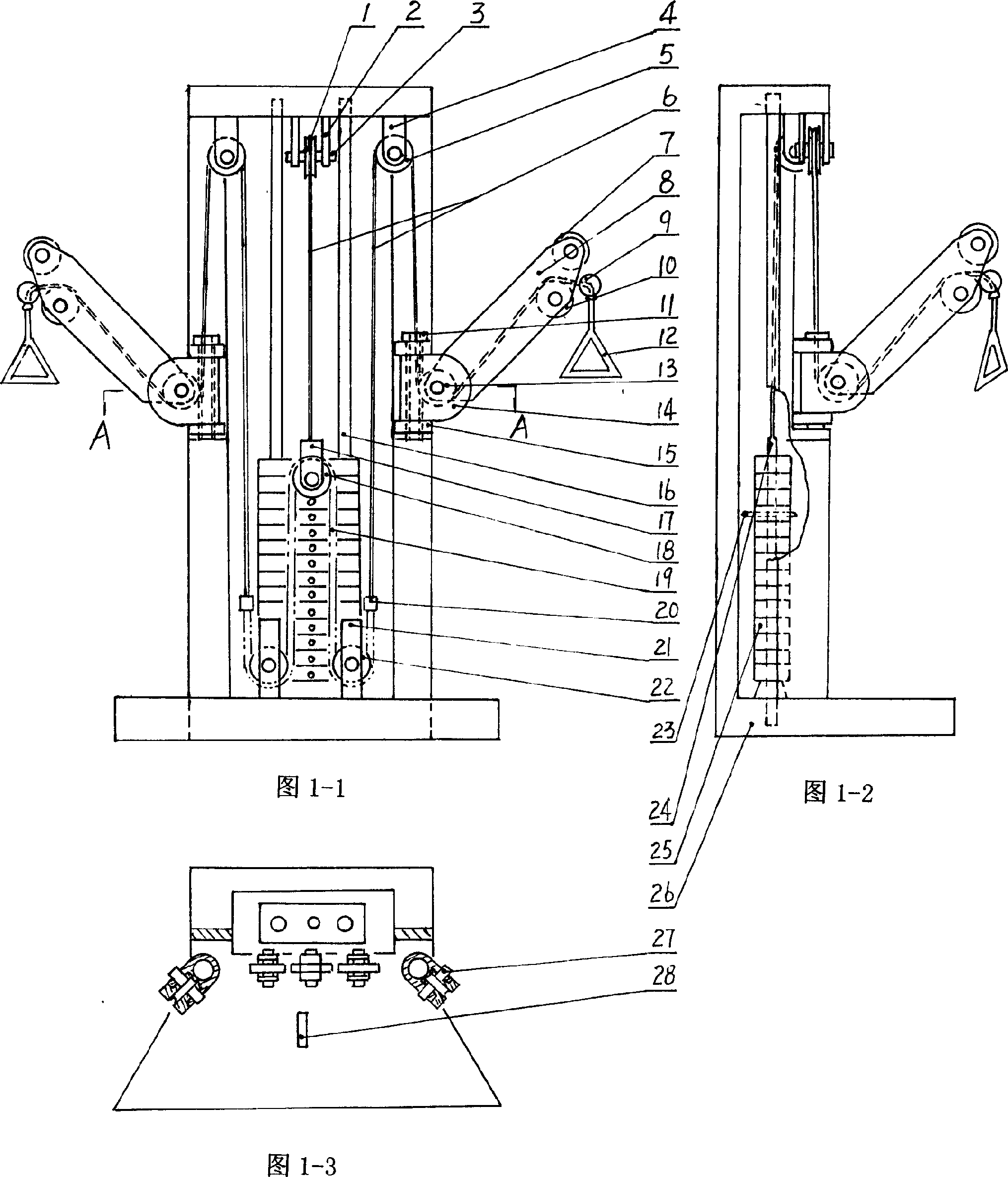
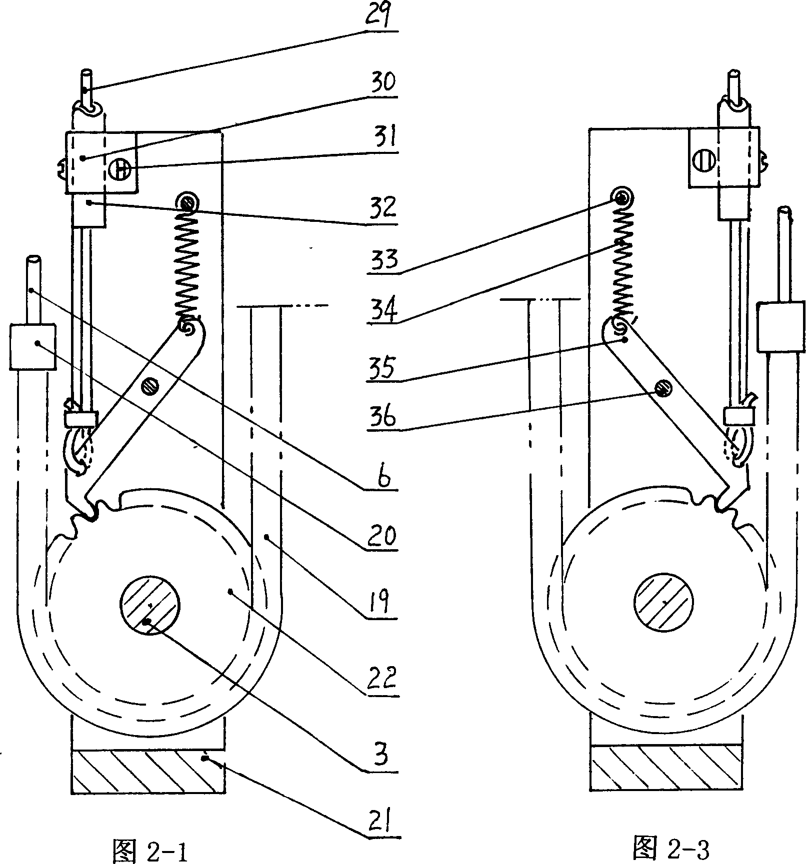
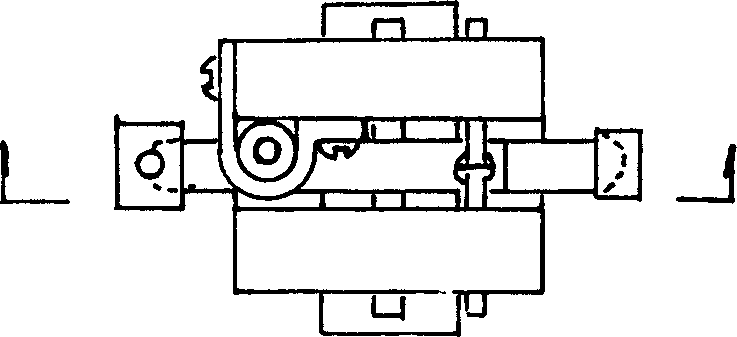
[0079] Example 1, as shown in Figure 1-1 to image 3 As shown, the multifunctional fitness equipment of the present invention is mainly composed of a frame, a counterweight mechanism, an action part, an adjustment mechanism, an auxiliary mechanism and a locking mechanism.
[0080] in:
[0081] The frame 26 constitutes the main body structure of the fitness equipment and plays the role of supporting other mechanisms.
[0082] The action part refers to the hook 12, which can change the direction and angle of the traction counterweight mechanism according to the different parts of the human body exercised.
[0083] Counterweight mechanism is mainly made of conduit 16, select lever 24, select pin 23, select iron 25.
[0084] The regulating mechanism is mainly composed of regulating arm 8, rotating arm 14, hollow rotating pin 11, bearing 15 (both sides are symmetrically arranged).
[0085] Auxiliary mechanism mainly is made of steel cable 6, pulley 1,5,7,10,13 and sprocket wheel...
Embodiment 2
[0109] Embodiment 2, as shown in Figures 4-1 to 4-4, compared with Embodiment 1, the difference between the multifunctional fitness equipment of the present invention lies in the structure of the clutch part of the locking mechanism.
[0110] The following embodiments are all improvements to the extended design of the clutch part of the locking mechanism, and the structure of the same part will not be described again.
[0111] The clutch part of this embodiment is mainly composed of a long pin 45 , a long pin seat 48 and a return spring 47 .
[0112] A plurality of holes are symmetrically opened along the circumferential direction of the sprocket 22 , and the long pin 45 can pass through a corresponding hole on the sprocket seat 21 to penetrate into one of the holes, thereby realizing the positioning of the sprocket 22 .
[0113] The long pin 45 is fixed on one side of the sprocket seat 21 by the long pin seat 48 through the screw 46 .
[0114]When the steel wire 29 was in a ...
Embodiment 3
[0116] Embodiment 3, as shown in FIG. 5-1 and FIG. 5-2 , the clutch part described in this embodiment is mainly composed of a brake disc 55 , a brake band 53 , a brake shoe 54 , a brake lever 50 and a tension spring 34 .
[0117] Brake discs 55 are provided on both sides of the sprocket 22 .
[0118] The brake band 53 is affixed with a brake shoe 54 and is arranged around a brake disc 55 . One end of brake band 53 is worn with pin 52 and fixes, and pin 52 can rotate freely in the hole of this end of brake band.
[0119] The other end of the brake band 52 is connected with one end of the brake lever 50 through a small pivot pin 51 .
[0120] The middle of the brake lever 50 penetrates the brake pin 49 , and the two ends of the brake pin 49 penetrate in the corresponding holes of the sprocket seat 21 .
[0121] The other end of brake lever 50 is connected with two relevant parts, and one is to penetrate the steel wire 29 in the brake line 30, the steel wire buckle 44 that is f...
PUM
 Abstract
Description
Claims
Application Information
 - R&D
- Intellectual Property
- Life Sciences
- Materials
- Tech Scout
- Unparalleled Data Quality
- Higher Quality Content
- 60% Fewer Hallucinations
Browse by: Latest US Patents, China's latest patents, Technical Efficacy Thesaurus, Application Domain, Technology Topic, Popular Technical Reports.
© 2025 PatSnap. All rights reserved.Legal|Privacy policy|Modern Slavery Act Transparency Statement|Sitemap|About US| Contact US: help@patsnap.com


