Heat storage type thawing device

A heat storage and snow melting technology, which is applied in the field of devices for melting roofs and road snow, and can solve problems such as subsidence of foundations

Inactive Publication Date: 2004-11-03
ミサワ環境技術
View PDF0 Cites 12 Cited by
  • Summary
  • Abstract
  • Description
  • Claims
  • Application Information

AI Technical Summary

Problems solved by technology

And spraying groundwater will also cause the problem of subsidence of the foundation

Method used


Image

  • Heat storage type thawing device
  • Heat storage type thawing device
  • Heat storage type thawing device

Examples


Embodiment Construction

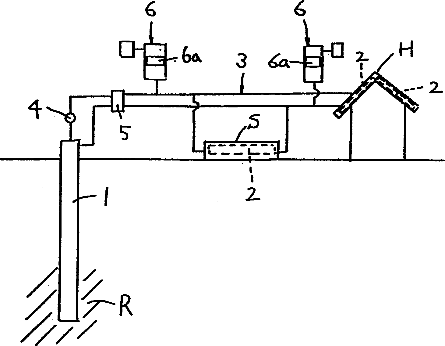
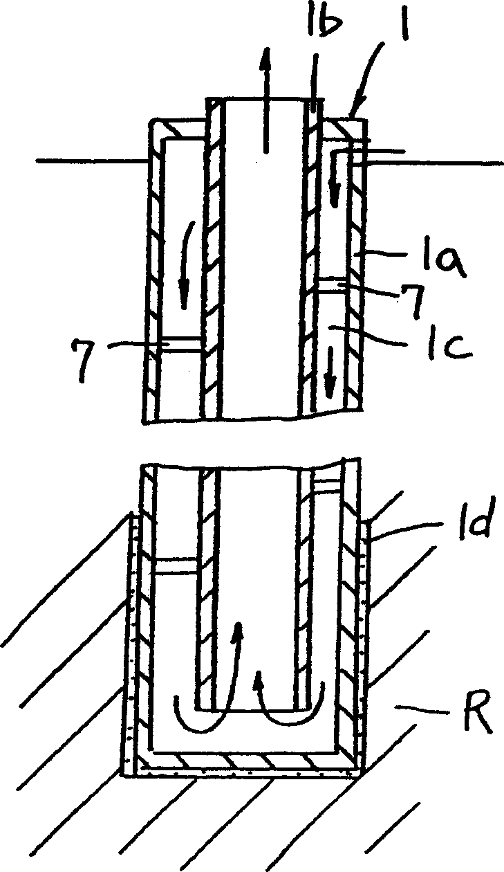
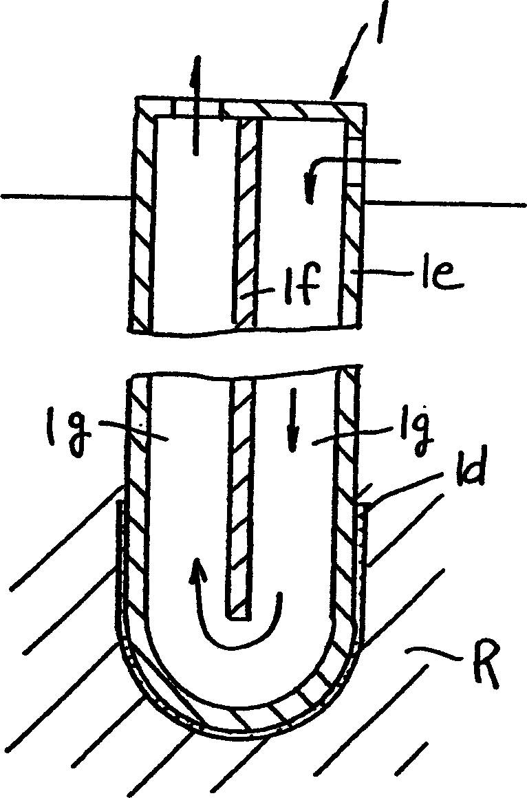
[0036] Embodiments of the thermal storage type snow melting device related to the present invention, such as Figure 1 to Figure 3 shown. In this device, the heat exchanger 1 , which circulates antifreeze inside and can exchange heat with the rock bed R, is buried vertically to the rock bed R as deep as 100m-200m. The snow-melting tray 2 is set in a place where the sun's rays can irradiate in summer, and the heat exchanger 1 and the snow-melting tray 2 are connected by a circulation pipe 3 provided with a pump 4, a switching valve 5 and an accumulator 6.

[0037] Then in summer, the solar energy is taken by the snow melting tray 2, and the solar energy is stored in the rock bed R through the heat exchanger 1. In winter, by switching the switching valve 5, the underground heat energy taken by the heat exchanger 1 and stored in the rock bed R is supplied to the snow-melting tray 2, and the snow-melting tray 2 can be used to melt the snow on the roof H and the road surface S.

...


PUM


Abstract

The heat accumulating snow thawing apparatus utilizes solar energy accumulated in summer to thaw snow in roof and road without fuel consumption and ground subsidence. Heat exchanger with internal circulating liquid is buried underground reach rock bed for heat exchange with rock bed, and snow thawing plates are set in where sun shines at least in summer, and circulating pipeline with pump, switching valve and accumulator is set in between. In summer, solar energy is acquired with the snow thawing plates and stored in the rock bed. In winter, the valve is switched for providing the accumulated heat from the rock bed to the snow thawing plates to thaw snow in roof and road.

Description

technical field [0001] The present invention relates to a device for storing solar energy in an underground bedrock R in summer and using underground thermal energy containing the thermal energy to melt snow on roofs and roads in winter. Background technique [0002] Conventionally, to clear snow off building roofs and roads, snow plows and shovels were used to remove snow, and snow was melted by spraying heated hot water and extracted groundwater. Contents of the invention [0003] Snow removal using snow plows and shovels does not melt the snow, but simply moves and accumulates it. Therefore, the snow that should accumulate has a problem that hinders daily life. Using heated hot water to melt snow can be expensive in fuel. The spraying of groundwater will also cause the problem of subsidence of the foundation. [0004] It is best to store abundant solar energy in summer. If this thermal energy can be used to melt snow in winter, the efficiency of snow melting can be im...

Claims


Application Information

Patent Timeline
Patent Type & Authority Applications(China)
IPC IPC(8): E01C11/26F24J2/34
CPCY02B10/20Y02E10/40
Inventor 洲泽昭已
Owner ミサワ環境技術
Why Eureka
Try Eureka