Micro fluid control chip laser inducing fluorometric analysis instrument

A laser-induced fluorescence and microfluidic chip technology, which is applied in the field of optical instruments, can solve the problems of difficult analysis, limited flexibility, and not opening the chip to the outside world, and achieve the effects of simple data calculation, widening the selection range, and convenient and reliable use

Inactive Publication Date: 2004-11-24
DALIAN INST OF CHEM PHYSICS CHINESE ACAD OF SCI
View PDF0 Cites 10 Cited by
  • Summary
  • Abstract
  • Description
  • Claims
  • Application Information

AI Technical Summary

Problems solved by technology

[0003] ① Focusing is manual, which is extremely inconvenient, and it is difficult to obtain better repeatability;
[0004] ②The emission wavelength is only 570 nanometers, which limits the choice of dyes and has great limitations;
[0005] ③The software has no current-time curve detection display, which makes it difficult to analyze if a fault occurs during operation;
Since t...

Method used


Image

  • Micro fluid control chip laser inducing fluorometric analysis instrument
  • Micro fluid control chip laser inducing fluorometric analysis instrument
  • Micro fluid control chip laser inducing fluorometric analysis instrument

Examples


Embodiment Construction

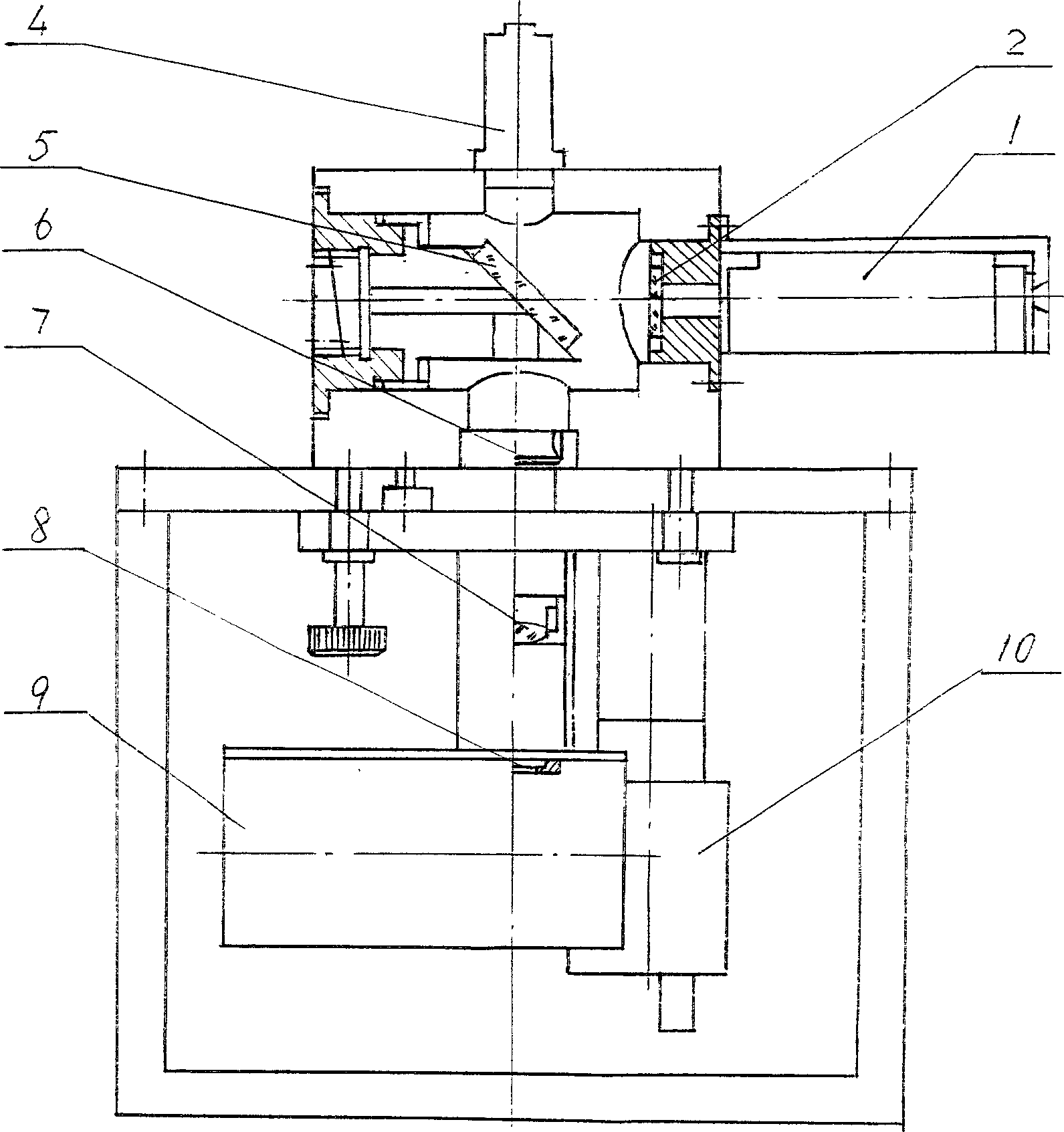
[0043] The composition of the microfluidic chip fluorescence analyzer includes an optical path, a module and an operating platform for circuit and high-voltage control, and its various functions are implemented through computer software.

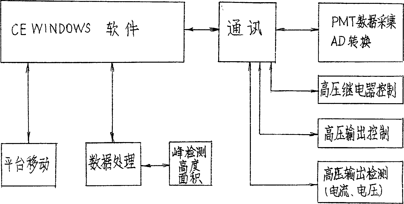
[0044] For the communication connection diagram of the computer software of this instrument, see image 3 .

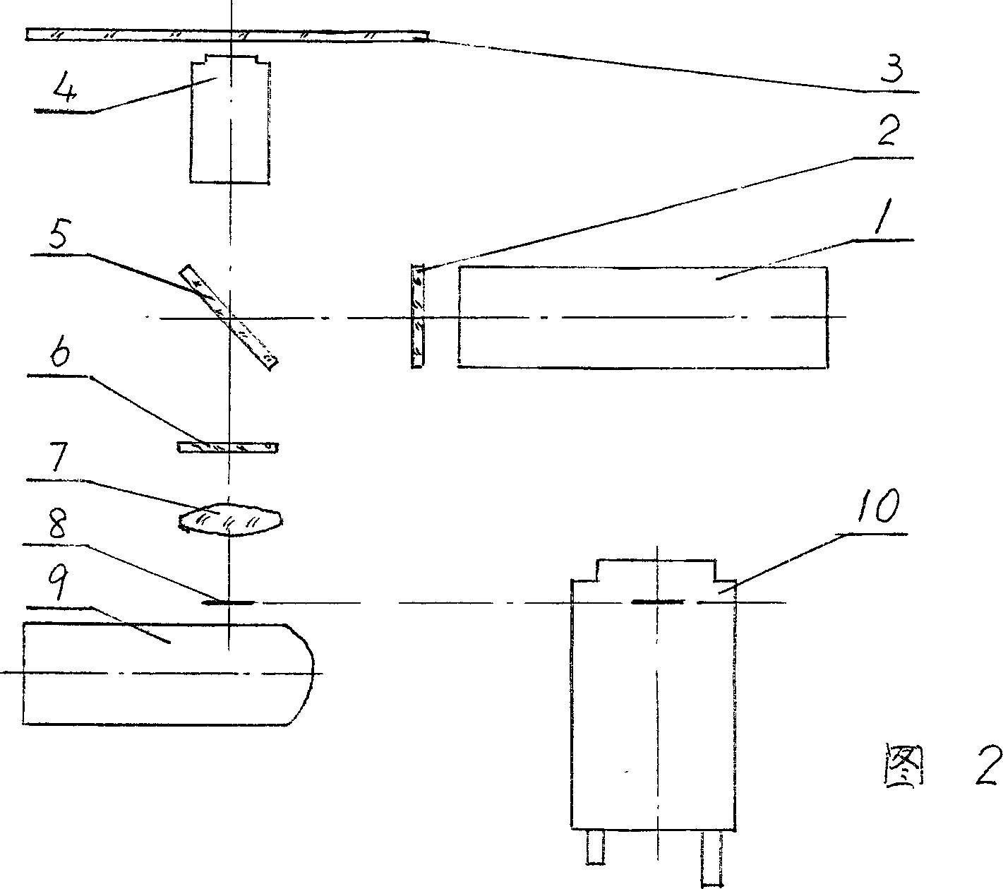
[0045] The principle optical path diagram of the instrument is shown in Figure 2.

[0046] The instrument is monitored by CCD, and the computer screen displays the focus; it uses a 532nm laser, and the light source and filter can be replaced to broaden the selection range of experimental dyes.

[0047] The instrument software operating system consists of three parts:

[0048] ①Separation control program, including time selection and voltage adjustment control of optical path mouse click focusing and separation process under CCD detection;

[0049] ②The data collection part is composed of the output voltage-time curve, current-time...


PUM


Abstract

The present invention includes optical path, circuit, computer and operation platform. The optical path includes light source, optical filters, objective, half-reflecting mirror, focusing lens, pinhole and photomultipler tube. The circuit includes the part for data collection of photomultipler tube, A/D converter, high voltage relay, high voltage output controller and high voltage output detection unit. The computer is connected to the circuit via communicator. The present invention features the computer with CE WINDOWS application software for parameter setting, peak detection and data processing.

Description

Technical field: [0001] The invention relates to an optical instrument in the field of analytical chemistry, a computer-controlled optical instrument. Background technique: [0002] The basic principle of the microfluidic chip analyzer produced by the Canadian Albert company is to use the 530nm laser generated by the semiconductor laser to pass through a filter to become relatively monochromatic light, pass through a half-transparent mirror and then irradiate the microscopic light through the objective lens. In the pipeline of the fluidic chip; if there is a fluorescent substance in the pipeline, it (they) will emit fluorescence of a certain wavelength after obtaining energy under the irradiation of the laser. Then, the fluorescence enters the optical circuit through the objective lens, and then passes through a filter The light of non-fluorescence wavelength is filtered out, and the fluorescence enters the photomultiplier tube through the pinhole, and after being amplified,...

Claims


Application Information

Patent Timeline
IPC IPC(8): G01N21/64G01N35/00
Inventor 周小棉戴忠鹏林炳承李义海
Owner DALIAN INST OF CHEM PHYSICS CHINESE ACAD OF SCI
Why Eureka
Try Eureka