Method and device for knotting the ends of a thread to flat articles

An object and flat technology, which is applied in the field of knotting on flat objects at the wire end, can solve problems such as limited working speed, complicated movement process, and complicated methods, and achieve the effect of improving working speed and simple device structure

Active Publication Date: 2004-12-01
茶叶包装专用机械两合公司
View PDF0 Cites 8 Cited by
  • Summary
  • Abstract
  • Description
  • Claims
  • Application Information

AI Technical Summary

Problems solved by technology

The vast majority of needle-based methods are very complex and thus limited in how fast they can work
The associated devices consist of a large number of parts whose movements are very complex and thus require considerable technical outlay especially for the control parts

Method used


Image

  • Method and device for knotting the ends of a thread to flat articles
  • Method and device for knotting the ends of a thread to flat articles

Examples


Embodiment Construction

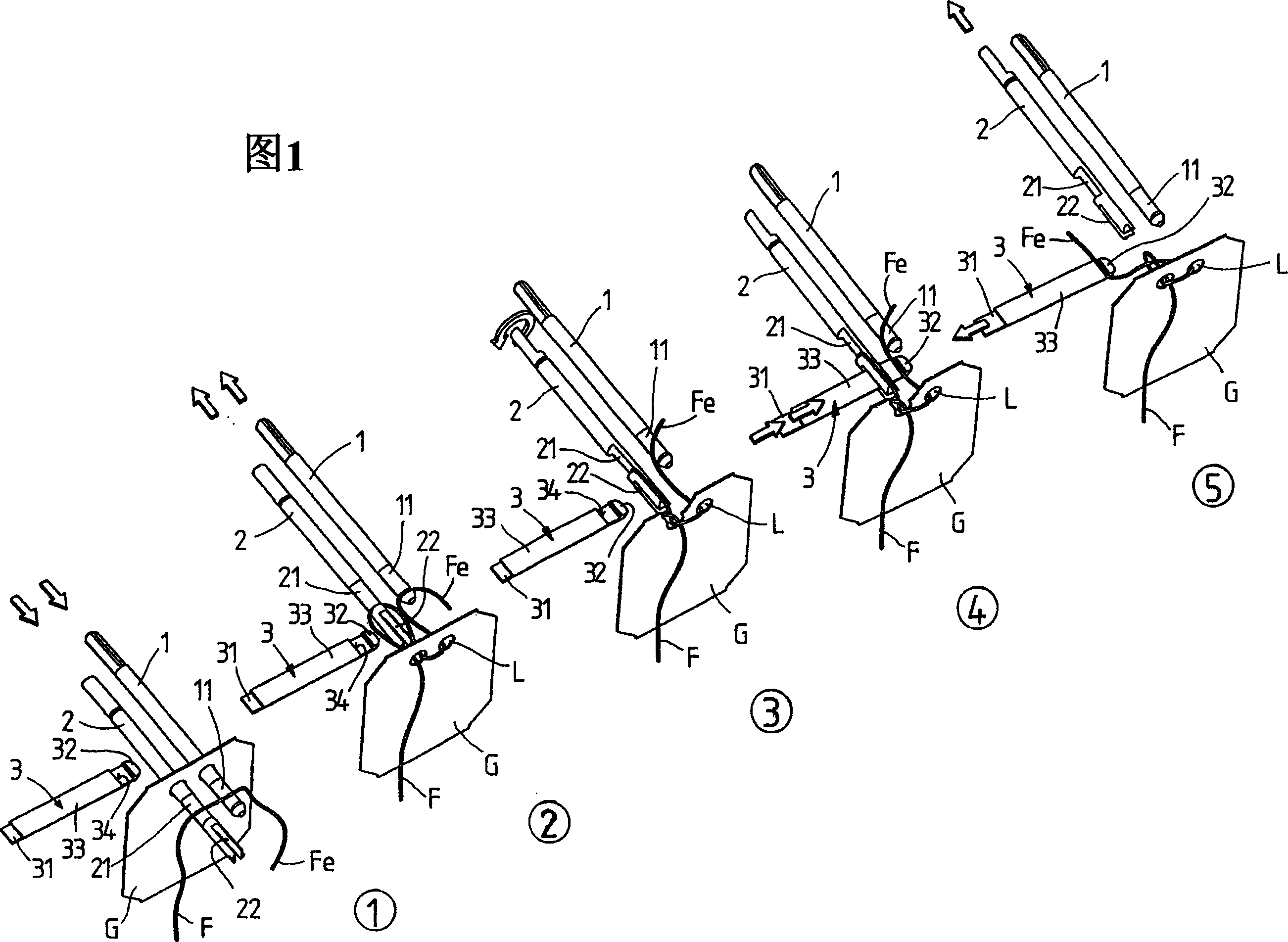
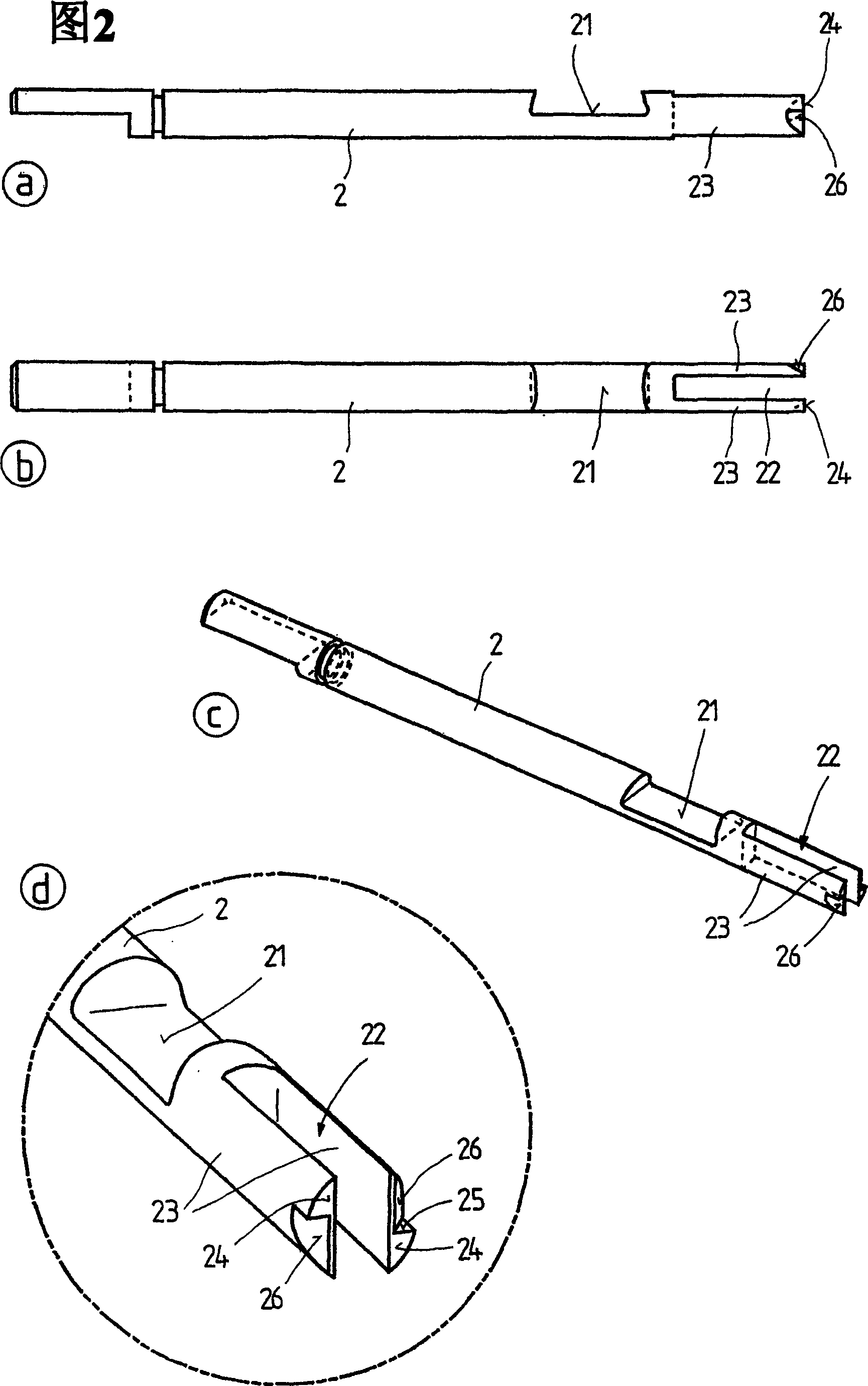
[0020] FIG. 1 shows a device for knotting a thread F end on a flat object G in the form of a label, which comprises three tools, namely a first rod 1 , a second rod 2 and a gripper 3 . These three tools are shown schematically and exploded in five different positions in FIG. 1 . FIG. 2 shows a side view (a), a top view (b), a perspective view (c) of the rod 2 and a detail (d) in relation to its end-side configuration.

[0021] As can be seen from FIG. 1 , the bars 1 and 2 are distributed parallel to and at a distance from each other; the gripper 3 moves at right angles to the plane in which the bars 1 and 2 are located.

[0022] As can be seen from Figure 1, the rod 1 moves between a front end position (see Figure 1.1) and a rear end position (see Figures 1.2-1.5). It has a hook-shaped notch 11 on the front end for receiving the thread F.

[0023] The second rod 2 also has such a notch 21 forming a hook, but the end of the second rod has a perforation formed as an opening 22...


PUM


Abstract

The invention relates to a method and a device for knotting the end of a thread to a flat object containing two spaced holes for the knot. The method provides the thread located in front of the holes is pulled to the other side of the object while forming loops, and in that the loop is rotated by at least 270 DEG . Subsequently the end of the thread is pulled through this loop and the knot that is formed is tightened. The device provides three tools, specifically two bars and a gripper.

Description

technical field [0001] The present invention relates to a method and a device for knotting a thread end on a flat object, in particular a teabag and / or a label for serving a beverage, having two spaced apart holes for knotting. Background technique [0002] A number of methods and devices are known for knotting wire ends on flat objects. Most of the needle-operated methods are very complicated and thus limited in their working speed. The associated devices consist of a large number of components whose motion sequences are very complex, so that a relatively high technical outlay is required, especially for the control components. [0003] Knots produced using known methods and devices are formed between a hole and a side of the flat object. The threads making up the knots are thus distributed in the direction of the fibers of the paper sheet making up the flat object. When the knot is stressed, it can cause the sheet to tear, especially if there is an opening for the threa...

Claims


Application Information

Patent Timeline
Patent Type & Authority Applications(China)
IPC IPC(8): D03J3/00B65B29/04
CPCB65B29/04
Inventor 斯特凡·兰贝茨曼弗雷德·豪尔斯迪特尔·维茨
Owner 茶叶包装专用机械两合公司
Why Eureka
Try Eureka