Magnetoresistive head and magnetic recording-reproducing apparatus
A technology of magnetoresistive magnetic head and magnetoresistive film, which is applied in the directions of magnetic recording, magnetic recording head, manufacturing magnetic flux sensitive magnetic head, etc., can solve the problems of reducing the bit length and the gap length of magnetic recording-reproducing device, etc.
- Summary
- Abstract
- Description
- Claims
- Application Information
AI Technical Summary
Problems solved by technology
Method used
Image

Examples
no. 1 example
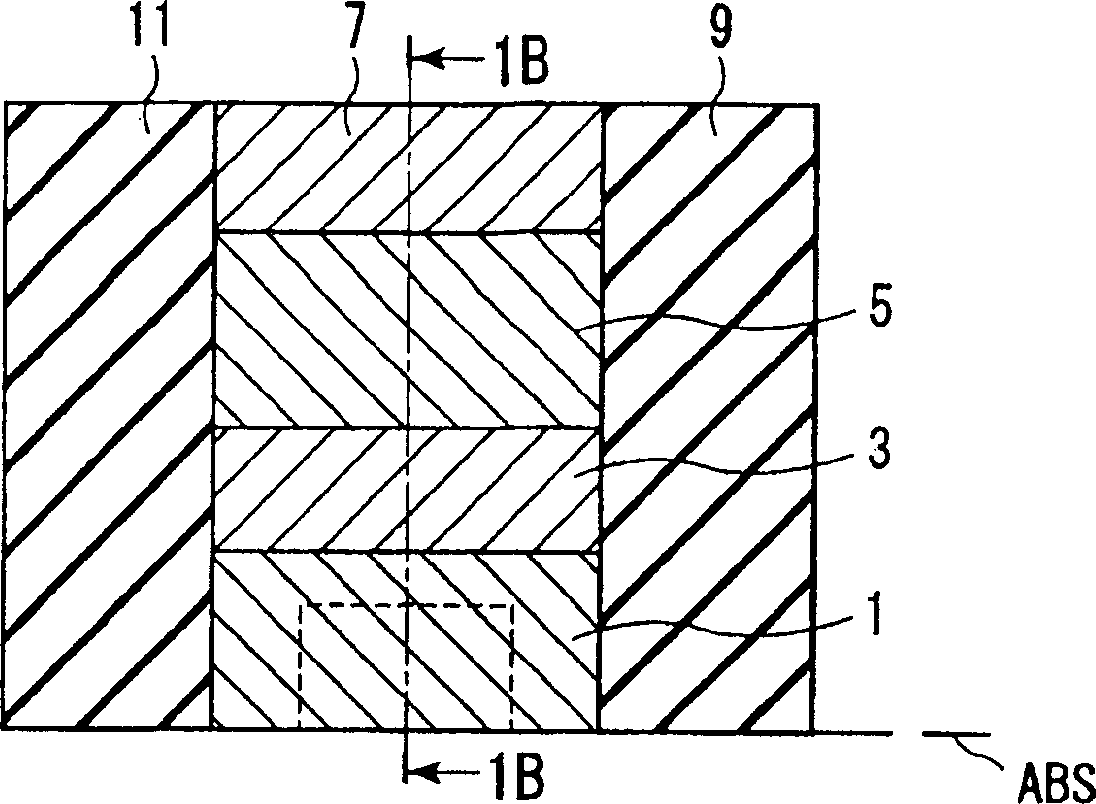
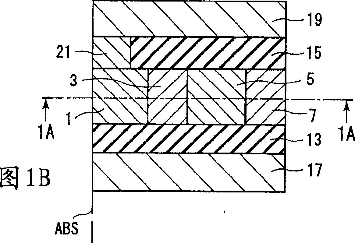
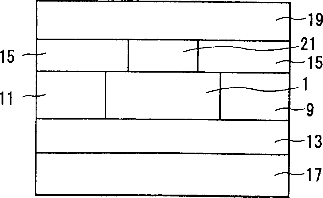
[0033] Next, a shielded GMR magnetic head will be described according to a first embodiment of the present invention. Figures 1A to 1C shows the structure of the shielded GMR magnetic head of the present embodiment, wherein, Figure 1A is a cross-sectional view of a GMR head along a direction parallel to the track width direction of a magnetic recording medium (not shown), and FIG. 1B is a cross-sectional view of a GMR head along a direction parallel to a track direction of a magnetic recording medium (not shown), and Figure 1C It is a plan view showing the GMR magnetic head viewed from the direction of the air bearing surface (ABS). Figure 1A is a cross-sectional view along line 1A-1A shown in FIG. 1B . The surface on the bottom side in the figure represents ABS. Figure 1B is along the Figure 1A The cross-sectional view shown on line 1B-1B. The surface on the left in the figure represents ABS.
[0034] The GMR magnetic head of the present embodiment includes an insulati...
no. 2 example
[0089] A GMR magnetic head according to a second embodiment of the present invention will be described below. Fig. 12A is a cross-sectional view of the GMR magnetic head along a direction parallel to the track width direction; Figure 12Bis a cross-sectional view of the GMR head along a direction parallel to the track direction; and Figure 12C is a plan view of the GMR head viewed from the ABS direction. Figure 12A is along the Figure 12B The cross-sectional view at line 12A-12A. The surface on the bottom side in the figure represents ABS. Figure 12B is a cross-sectional view along line 12B-12B in FIG. 12A. The surface on the left in the figure represents ABS. In addition to the components shown in FIGS. 12A to 12C, the GMR magnetic head of the present invention includes an insulating nonmagnetic film surrounding the above components and wiring for connecting the SV element with a detection circuit and the like.
[0090] Such as Figure 12B and 12C As shown, the bot...
no. 3 example
[0099] Figure 13 is a cross-sectional view showing the structure of a GMR magnetic head according to a third embodiment of the present invention. In this embodiment, the nonmagnetic interlayer 3 is formed on the insulating layer 13 , and the magnetization free layer 1 and the magnetization pinned layer 5 are formed on the nonmagnetic interlayer 3 . The magnetization free layer 1 and the magnetization pinned layer 5 are formed to be separated from each other and electrically insulated from each other by the insulating film 69 . The detection current for the resistance of the magnetostatic GMR element flows through the first electrode 7 , the magnetized pinned layer 5 , the nonmagnetic intermediate layer 3 , the magnetized free layer 1 , the pillar electrode 21 and the upper magnetic shield 19 .
[0100] In this embodiment, the magnetization free layer 1 and the magnetization pinned layer 5 are connected to the same surface of the nonmagnetic intermediate layer 3 . It is suff...
PUM
| Property | Measurement | Unit |
|---|---|---|
| thickness | aaaaa | aaaaa |
| thickness | aaaaa | aaaaa |
| thickness | aaaaa | aaaaa |
Abstract
Description
Claims
Application Information
 - Generate Ideas
- Intellectual Property
- Life Sciences
- Materials
- Tech Scout
- Unparalleled Data Quality
- Higher Quality Content
- 60% Fewer Hallucinations
Browse by: Latest US Patents, China's latest patents, Technical Efficacy Thesaurus, Application Domain, Technology Topic, Popular Technical Reports.
© 2025 PatSnap. All rights reserved.Legal|Privacy policy|Modern Slavery Act Transparency Statement|Sitemap|About US| Contact US: help@patsnap.com