Electromagnetic relay

A technology of electromagnetic relays and electromagnetic units, applied in the direction of electromagnetic relays, relays, detailed information of electromagnetic relays, etc., can solve the problems of reducing productivity, reducing the number of turns of coil winding, reducing switching characteristics, etc., to prevent productivity decline and maintain switching characteristics , Guarantee the effect of insulating properties

Active Publication Date: 2004-12-01
ORMON CORP
View PDF1 Cites 4 Cited by
  • Summary
  • Abstract
  • Description
  • Claims
  • Application Information

AI Technical Summary

Problems solved by technology

[0005] However, when the correcting coil is to be mounted on the magnetic pole portion of the iron core in the above-mentioned electromagnetic relay, it is inevitable to increase the height dimension of the entire electromagnetic device.
On the other hand, the requirement to make the device compact limits the height dimension, so it is necessary to shorten the height dimension of the correction coil correspondingly in the bobbin portion of the bobbin.
As a result, the number of turns that the coil can be wound on the bobbin portion is reduced, so that the predetermined required driving force cannot be obtained
Correspondingly, the switching characteristics are reduced, and the adjustable tolerance range is also narrowed due to the reduced switching characteristics
Therefore, the problem with this technology is that it requires high precision parts and assembly accuracy, which reduces productivity.
However, if the coil drawing groove is to be formed on the above-mentioned flange portion, the thickness of the flange portion will be increased, thereby increasing the overall height dimension.
Correspondingly, if the height dimension of the electromagnetic relay is to be limited, the bobbin must be shortened, thus bringing about problems similar to those described above

Method used


Image

  • Electromagnetic relay
  • Electromagnetic relay
  • Electromagnetic relay

Examples


Embodiment Construction

[0016] Refer to the attached figure 1 to 6 describe the embodiment modes of the present invention.

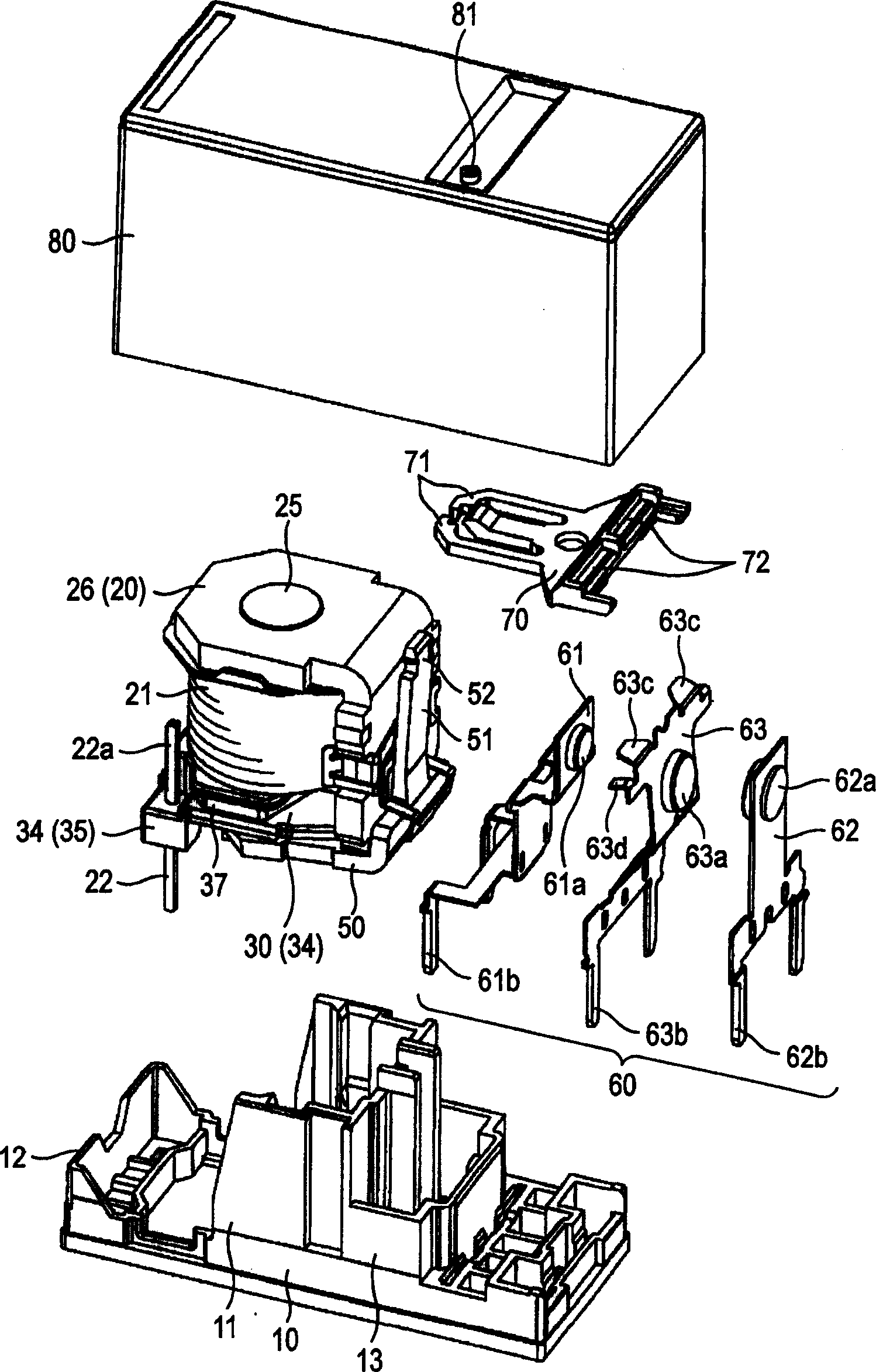
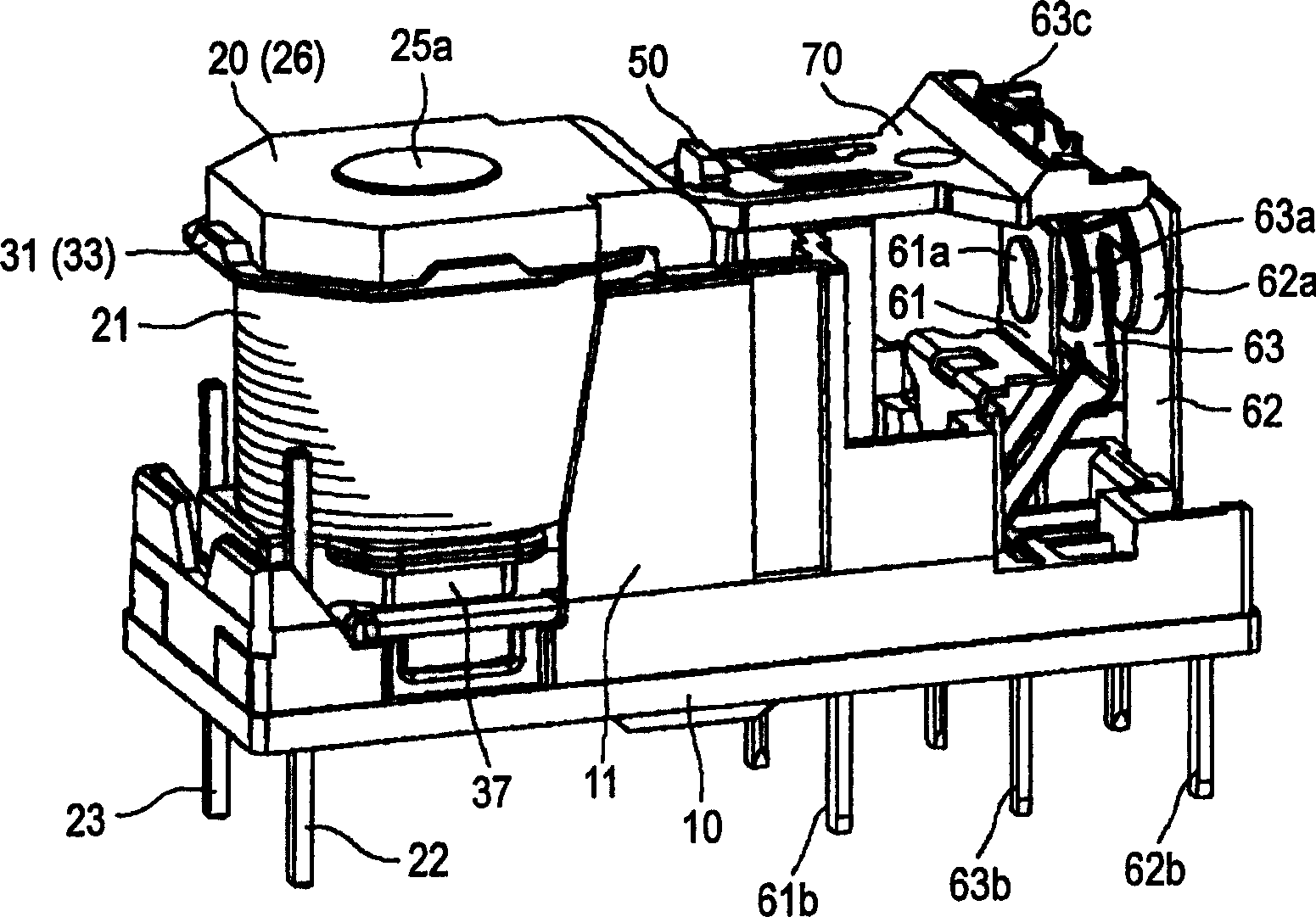
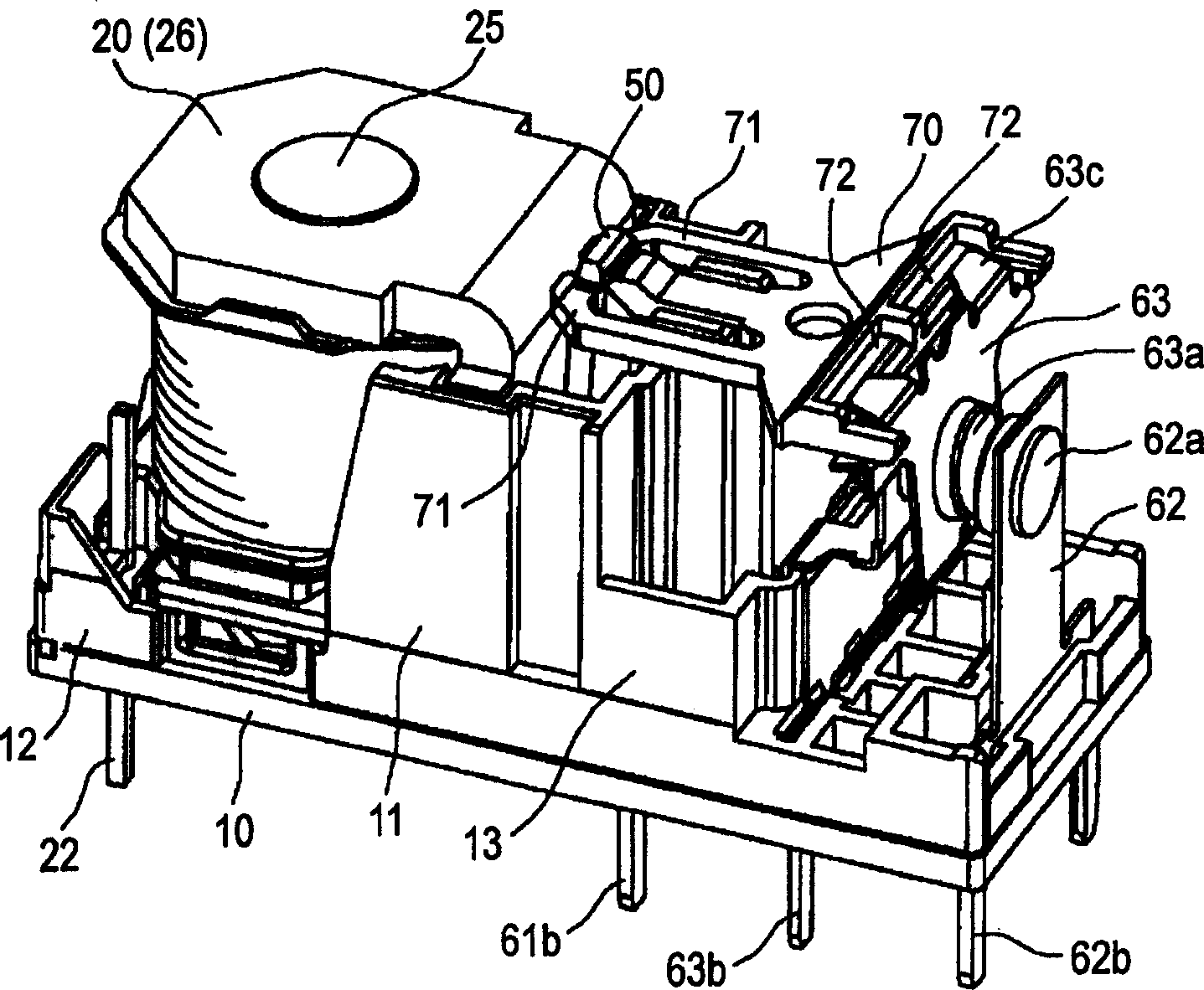
[0017] Such as figure 1 As shown, the implementation mode of the electromagnetic relay of the present invention is schematically composed of a base 10 , an electromagnetic unit 20 , a contact mechanism 60 , a card 70 and a cover 80 .

[0018] In the base 10 , the first insulating wall 11 is substantially square-bracket-shaped in plan view, and protrudes at the center of the upper surface of the base 10 . Furthermore, the second insulating wall 13 protrudes behind the first insulating wall 11 . On the other hand, a sealing wall 12 protrudes along an edge portion on one side of the upper surface of the base 10 to prevent the sealant from entering. The electromagnetic unit 20 is provided between the first insulating wall 11 and the second insulating wall 13 . On the other hand, the contact mechanism 60 is provided behind the first insulating wall 11 .

[0019] Such as image...


PUM


Abstract

The invention provides an electromagnetic relay excellent in insulating property and high in opening and closing characteristics and productivity. Therefore, a pair of pedestal portions for coil terminals are arranged in the outer circumferential edge portion of the lower flange portion of a spool. A coil drawing-out groove continuously connected to the upper face of the above pedestal portion for a coil terminal is formed along the outer circumferential edge portion of the above lower flange portion. A storing concave portion able to store a shading coil attached to a magnetic pole portion of an iron core projected from a central hole of the above spool is formed on the lower face of the above lower flange portion.

Description

technical field [0001] The invention relates to an electromagnetic relay, in particular to a high-voltage electromagnetic relay with a shading coil. Background technique [0002] In the conventional structure, the device is required to be made compact as an electromagnetic relay, and therefore, the height of the device is limited (eg, Patent Document 1). [0003] [Patent Document 1: JP-A-11-16472] [0004] That is, in this electromagnetic relay, the electromagnetic unit stands upright on one side of the upper surface of the base, and the contact mechanism is provided on the other side of the upper surface of the base. Based on the magnetizing force and demagnetizing force of the above-mentioned electromagnetic unit, a moving iron piece is rotated, and the contact mechanism is operated by the card. [0005] However, when the correcting coil is to be mounted on the magnetic pole portion of the iron core in the above electromagnetic relay, it is inevitable to increase the hei...

Claims


Application Information

Patent Timeline
Patent Type & Authority Applications(China)
IPC IPC(8): H01H50/44H01H50/14H01H50/46H01H50/64
CPCH01H2050/446H01H50/46H01H50/443H04M1/04
Inventor 田中弘泰真田博纪山崎弘章
Owner ORMON CORP
Why Eureka
Try Eureka