System and method for stabilizing spine

a spine and system technology, applied in the field of spine system stabilization, to achieve the effect of keeping the system height small

Inactive Publication Date: 2006-08-31
INION
View PDF50 Cites 37 Cited by
  • Summary
  • Abstract
  • Description
  • Claims
  • Application Information

AI Technical Summary

Benefits of technology

[0008] The invention provides the advantage that the fixation screw can be arranged to such a position relative to the fixation plate that the fixation screw and thus also the fixation plate can be fixed to the bone tissue in the best possible manner taking into consideration medical and operational criteria.
[0009] An idea of an embodiment of the invention is that the pre-drill hole is a through hole that extends from the top surface of the plate to the bottom surface. An advantage is that, in a through hole, it is very easy to make a fixation hole whose center axis is coaxial with the center axis of the pre-drill hole.
[0010] An idea of an embodiment of the invention is that the pre-drill hole is a blind hole that extends to a distance from the bottom surface of the plate. An advantage is that the making of the fixation hole is then essentially as easy in any direction.
[0011] An idea of an embodiment of the invention is that the top surface of the fixation plate has a countersink and that the head of the fixation screw is designed with respect to the countersink in such a manner that it does not form an essential protuberance above the plane of the top surface of the fixation plate. This provides the advantage that the height of the system can be kept as small as possible, which means that it disturbs the neighboring tissue as little as possible.
[0012] An idea of an embodiment of the invention is that the thread of the threaded section of the fixation screw is arranged to be changeable so that the height of the screw ridge is greater in the section closer to the distal end than in the section further away from the distal end. This provides the advantage that a high ridge fastens optimally to the cancellous bone, whereas a low ridge fastens optimally to cortical bone.

Problems solved by technology

In this solution, as in other prior art arrangements, it may be problematic to arrange the fixation screws in such a manner that the fixation plate fastens appropriately to the bone tissue.

Method used


Image

  • System and method for stabilizing spine
  • System and method for stabilizing spine
  • System and method for stabilizing spine

Examples


Embodiment Construction

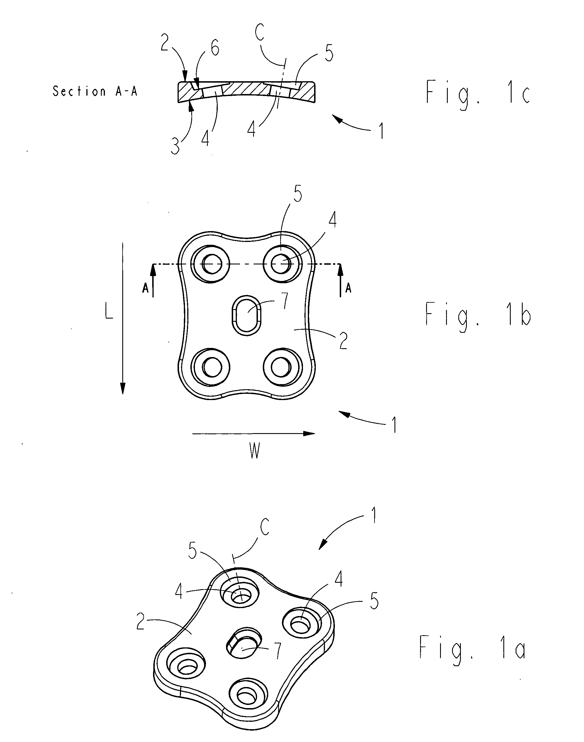
[0023]FIG. 1a is a schematic representation of a fixation plate belonging to the arrangement of the invention in perspective, FIG. 1b shows the same fixation plate from the direction of the top surface, and FIG. 1c shows it from the side in cross-section along section A-A. It should be noted that the fixation plate is in later on referred to as ‘plate’.

[0024] The plate 1 is preferably made of a biodegradable polymer material absorbing into the organ system that is prepared by polymerising or copolymerising for instance lactic acid, L-lactide, D-lactide, D,L-lactide, mesolactide, glycolic acid, glycolide or a cyclic ester copolymerised with lactide, or of any other corresponding material known per se to a person skilled in the art, which will not be discussed in this context in greater detail. Other suitable biodegradable polymers, copolymers and polymer mixtures are listed in the following publications, for instance: [0025]“Encyclopedic Handbook of Biomaterials and Bioengineering, ...


PUM


Abstract

A system and method for stabilizing the spine. The system comprises a fixation screw with a threaded section, and a fixation plate with a top and bottom surface. The fixation plate has a pre-drill hole arranged on the side of the top surface, and with the pre-drill hole, an actual fixation hole is made to the plate. The fixation hole is made when the plate is arranged at its future fixation point on the surface of bone tissue such that the fixation hole forms a first angle relative to the plate, whose size is selectable from several alternatives within certain limit values. The threaded section of the fixation hole is made during the same work phase as the threaded section in the bone tissue.

Description

BACKGROUND OF THE INVENTION [0001] The invention relates to a system for stabilizing the spine, especially the cervical spine, which arrangement comprises a fixation plate and fixation screws with which the fixation plate is fastened to threaded holes made in the bone. Both the fixation plate and screws can be made of a biodegradable material that dissolves in the organ system. [0002] The invention further relates to a method for stabilizing the spine, especially the cervical spine, in which method a stabilizing fixation plate is fastened through fixation screws to the part of the spine or cervical spine that is to be stabilized. [0003] Various injuries may be caused to the spine due to degeneration, tumors, and fractures and dislocations caused by physical trauma. In some operations directed to the spine, fixation plates are used that are fastened to the bone tissue of the spine by means of fixation screws arranged through fixation holes in the fixation plate. Cervical spine operat...

Claims


Application Information

Patent Timeline
Patent Type & Authority Applications(United States)
IPC IPC(8): A61B17/56A61B17/58
CPCA61B17/1728A61B17/8057A61B17/8625A61B17/8645A61B2017/00004A61B2017/00862A61F2/30749A61F2/44A61F2002/30261
Inventor HAPPONEN, HARRIVUORISALO, VESA
Owner INION
Why Eureka
Try Eureka