Piezoelectric transformer, power supply circuit and lighting unit using the same
A technology of piezoelectric transducers and piezoelectric ceramics, applied in lighting devices, components of piezoelectric devices or electrostrictive devices, piezoelectric/electrostrictive/magnetostrictive devices, etc., can solve the problem of electrical connection structures Complicated, difficult electrical connections, etc.
- Summary
- Abstract
- Description
- Claims
- Application Information
AI Technical Summary
Problems solved by technology
Method used
Image

Examples
no. 1 example
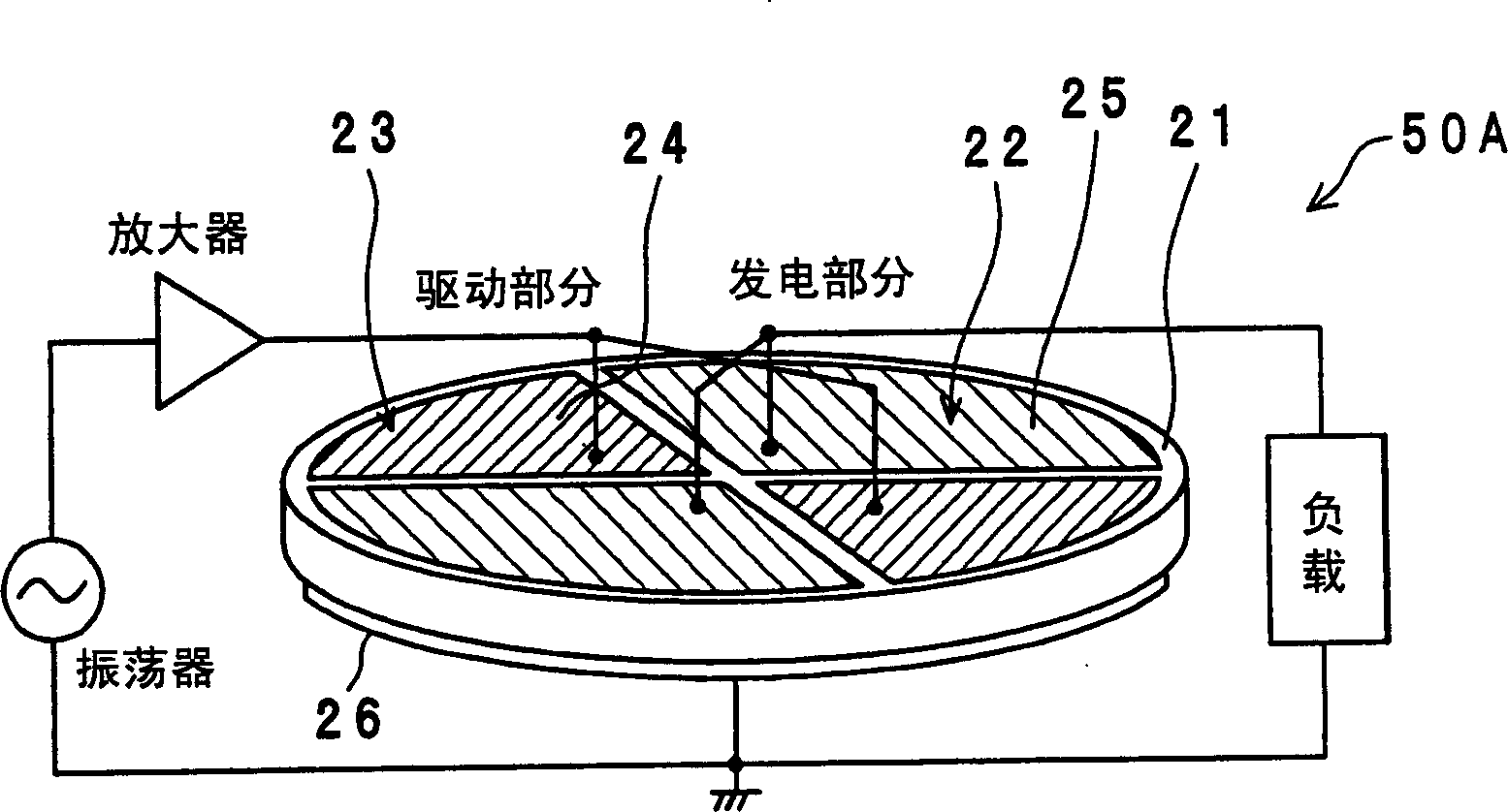
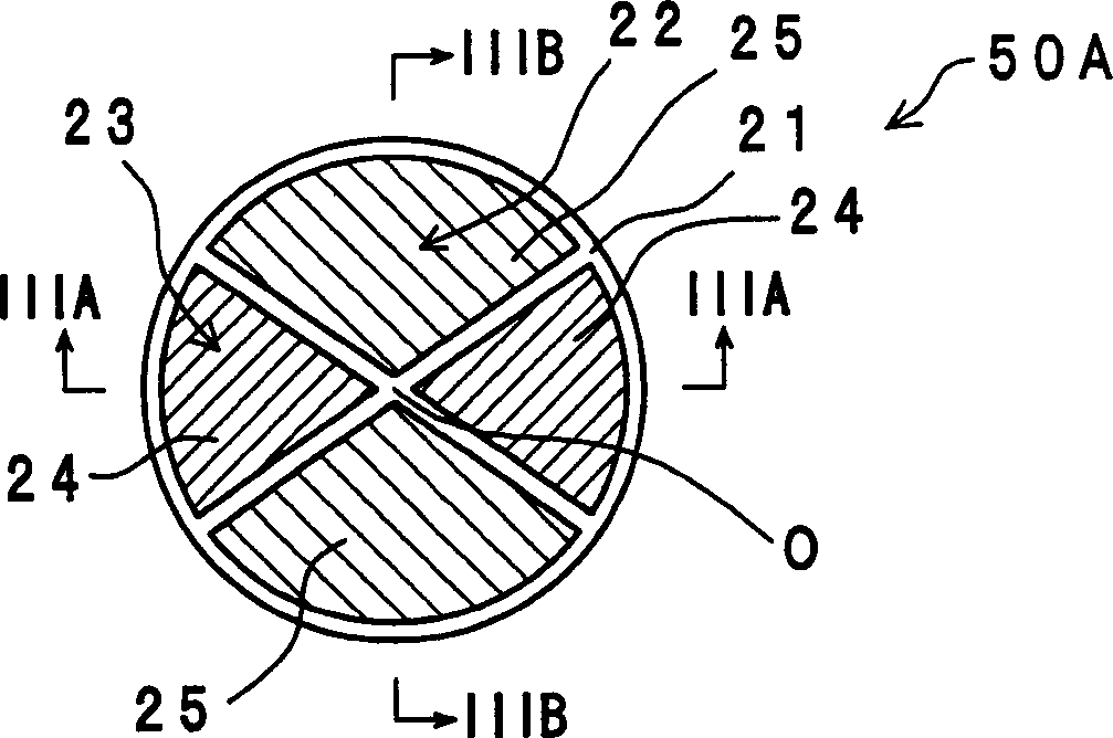
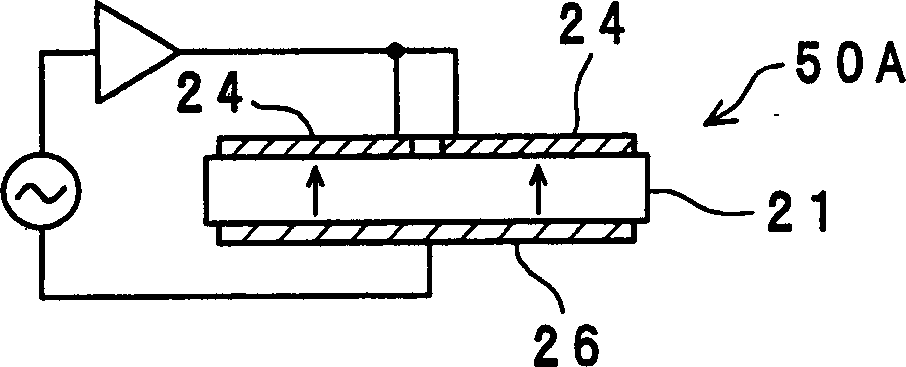
[0050] figure 1 is a perspective view of a piezoelectric transducer 50A of the first embodiment of the present invention, figure 2 is a top plan view of the piezoelectric transducer 50A. Figure 3A and 3B are along figure 2 The sectional view taken along the lines IIIA-IIIA and IIIB-IIIB. As shown in these figures, the piezoelectric transducer 50A includes a piezoelectric ceramic disk 21 whose one side and the other side are opposed to each other in the thickness direction. A pair of low-impedance portions 22 serving as a power generation portion or a driving portion are provided in the piezoelectric ceramic disk 21 symmetrically with respect to the central axis of the piezoelectric ceramic disk 21 . In addition, a pair of high impedance portions 23 serving as a driving portion or a power generation portion are provided on the piezoelectric ceramic disk 21 symmetrically about the central axis of the piezoelectric ceramic disk 21 and electrically separated from the low i...
no. 2 example
[0073] Figure 11A and 11B These are a top plan view and a bottom plan view of a piezoelectric transducer 50B of the second embodiment of the present invention, respectively. Figure 12 is along Figure 11A Sectional view taken along line XII-XII. piezoelectric transducer 50B with Figure 8 The piezoelectric transducer 50A" is different in the following points. That is, as shown in FIGS. An electrode 25a and the third electrode 24a are used to contact the support member 35, and a circular area 27b is also arranged on the other side of the piezoelectric ceramic disc 21, and the second electrode 25b and the fourth electrode are not formed in this area. 24b for contacting with another support member 35 .
[0074] Figure 13B A piezoelectric transformer of a comparative example of the piezoelectric transformer 50B is shown. in such as Figure 13B As shown, when the common electrode 26 is formed on the entire other surface of the piezoelectric ceramic disk 21 in the same ma...
no. 3 example
[0079] Figure 14 A top plan view of a piezoelectric transducer 50C according to a third embodiment of the present invention. Figure 15A , 15B and 15C are respectively along Figure 14 The cross-sectional views taken by the XVA-XVA line, XVB-XVB line and XVC-XVC line in Such as Figure 15B As shown, a plurality of electrode layers 29 and piezoelectric layers 30 are alternately stacked in the thickness direction of each low impedance portion 22 . Each electrode layer 29 is located at each opposing portion exposed on one side wall surface of each piezoelectric layer 30 so as to be connected to a side electrode 31 a formed on one side wall surface of each piezoelectric layer 30 . at the same time as Figure 15C As shown, the remaining electrode layers 29 are exposed to the other wall surface of each piezoelectric layer 30 to be connected to the side electrode 31b formed on the other side wall surface of each piezoelectric layer 30 .
[0080] Such as Figure 14 Shown in and...
PUM
 Abstract
Description
Claims
Application Information
 - R&D Engineer
- R&D Manager
- IP Professional
- Industry Leading Data Capabilities
- Powerful AI technology
- Patent DNA Extraction
Browse by: Latest US Patents, China's latest patents, Technical Efficacy Thesaurus, Application Domain, Technology Topic.
© 2024 PatSnap. All rights reserved.Legal|Privacy policy|Modern Slavery Act Transparency Statement|Sitemap