

Prestressed concrete continuous truss frame arched bridge
A concrete and prestressed technology, applied in the field of continuous truss arch bridges, can solve the problems of large tensile stress of inclined rods and vertical rods, unfavorable driving comfort, and reduced durability of composite arch bridges, so as to reduce deflection and vibration and improve driving effect. , improve the overall effect
Inactive Publication Date: 2004-12-22
郑锦文
View PDF0 Cites 14 Cited by
- Summary
- Abstract
- Description
- Claims
- Application Information
AI Technical Summary
Problems solved by technology
However, in the history of more than 20 years since its establishment, some problems have not been fundamentally resolved, that is, there are expansion joints at the junction of the side truss cantilever beams and the middle truss arch. Due to the complete disconnection of the upper chord, the main The integrity of the upper structure of the hole is poor. When heavy vehicles pass by quickly, there will be obvious vibration on the bridge, and its dynamic performance is worse than that of cast-in-place box arch bridges.
This makes the truss composite arch bridge only used with caution on secondary roads and limited to highways
[0003] The fundamental reasons for the above-mentioned defects in the truss composite arch bridge are: (1) the lower chord at the expansion joint is subjected to complex internal forces of compression, bending, shearing, and torsion, and the negative bending moment and tensile stress at the upper edge are relatively large; (2) the diagonal bar at the expansion joint 1. The tensile stress of the vertical bar is very large, and it is difficult to solve the problem fundamentally by using the existing means - strengthening ordinary steel bars and prestressing force, so that the web bar of the completed bridge will inevitably have cracks at this place, which is the cantilever beam and truss arch (3) Since the middle truss arch is a flat arch, the positive bending moment of the vault and the tensile stress at the lower edge are relatively large, so that the final deflection of the vault is larger than that of the box arch bridge. , setting a vertical curve is not conducive to driving comfort
Method used
View moreImage
Smart ImageViewing Examples

Examples
Embodiment Construction
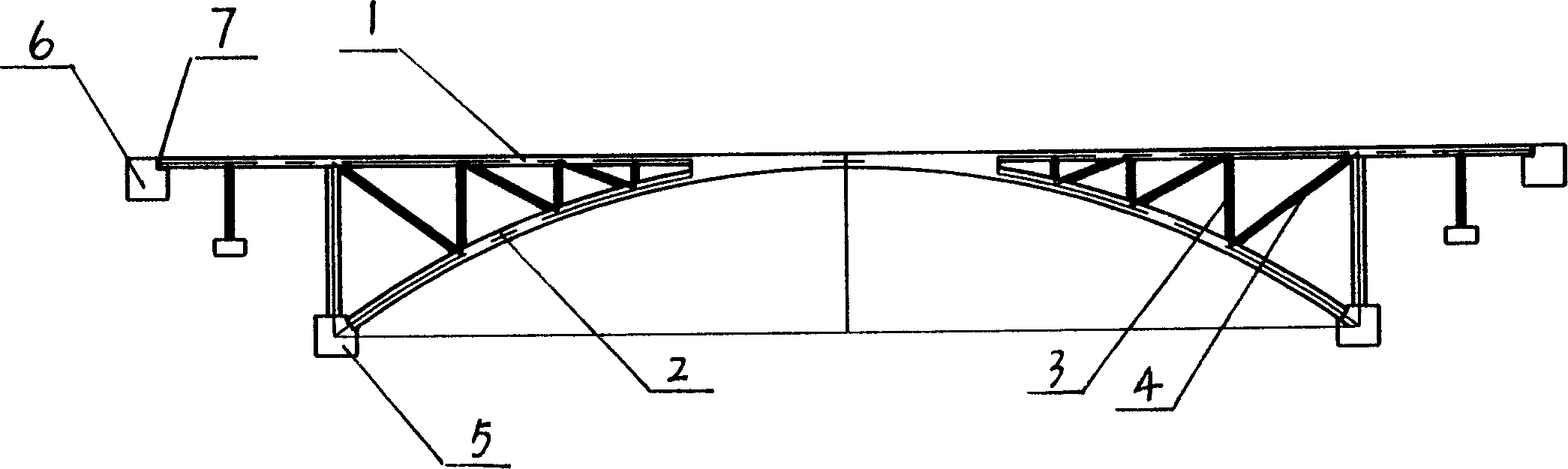
[0008] Embodiment of the present invention: the two ends of the lower chord (2) are supported on the abutment (5), the vertical bar (3) is a single vertical bar, and the vertical bar (3) and the inclined bar (4) are supported and connected on the upper chord (1 ) and the lower chord (2), the upper chord (1) is made into a whole continuous rigid-tie beam, the two ends of which are hinged on the abutment anchor wall (6) during construction, the two are separated during use, and the upper chord (1) ) and an expansion joint (7) is left between the abutment anchor wall (6).
Login to View More PUM
 Abstract
The arch bridge is composed of upper chord, lower chord, upright posts, inclined bars, anchoring wall at bridge abutment. Supported by arch support, lower chord through upright posts, inclined bars supports upper chord. The upper chord as a continuous beam is articulated on anchoring wall at bridge abutment through hinges at two ends. There is contraction-joint between upper chord and anchoring wall at bridge abutment. The invention raises integrity of bridge, reduces deflection, vibration and jigging motion providing advantages of improving trafficked effect and durability of bridge. Comparing with box ribbed arch bridges, truss bridges etc, the invented arch bridge possesses general superiorities suitable to use in each classified highways.
Description
Technical field: [0001] The invention relates to a bridge, in particular to a continuous truss arch bridge. technical background: [0002] In the prior art, the truss-type composite arch bridge has a high degree of safety during the cantilever construction process across high canyons and deep valleys. After the bridge is completed, the cost per unit area is relatively low, and it has obvious advantages in the arch bridge without support construction. However, in the history of more than 20 years since its establishment, some problems have not been fundamentally resolved, that is, there are expansion joints at the junction of the side truss cantilever beams and the middle truss arch. Due to the complete disconnection of the upper chord, the main The integrity of the upper structure of the hole is poor. When heavy vehicles pass by quickly, there will be obvious vibration on the bridge, and its dynamic performance is worse than that of the cast-in-place box arch bridge. This m...
Claims
Login to View More Application Information
Patent Timeline
 IPC IPC(8): E01D4/00
Inventor郑锦文
Owner郑锦文